Paper stacking device and image forming system

a stacking device and paper technology, applied in the field of paper stacking devices and image forming systems, can solve the problems of paper sticking, paper float, difficulty in appropriately adjusting air volume, etc., and achieve the effect of suppressing the sticking of ejected paper and satisfying productivity

Active Publication Date: 2020-05-21
KONICA MINOLTA INC
View PDF0 Cites 6 Cited by
  • Summary
  • Abstract
  • Description
  • Claims
  • Application Information

AI Technical Summary

Benefits of technology

[0007]The present invention has been made in view of the circumstances described above, and it is an object of the present invention to provide a paper stacking device and an image forming system that are capable of stacking paper with satisfactory productivity while suppressing the sticking of ejected paper.

Problems solved by technology

Therefore, techniques disclosed in JP 2014-40326 A, JP 2014-105081 A, and JP 2014-47047 A have a problem in which it is difficult to appropriately adjust air volume.
For example, an excessively weak flow of air fails to cause paper to float.
In contrast, an excessively strong flow of air raises paper, and the misalignment of paper occurs.
In addition, in a technique disclosed in JP 2011-84359 A, the holder is rotationally moved in upward and downward directions with a rotary shaft along the paper width direction as a center, and therefore the following inconvenience occurs according to the length of the holder.
For example, in a case where the holder is long, it takes longer time to retreat from the first position to the second position, and there is a possibility of a reduction in productivity.
In contrast, in a case where the holder is short, a front-end side of paper having a large size in the paper ejection direction hangs down from the holder, and there is a possibility of the occurrence of sticking onto uppermost paper.

Method used


Image

  • Paper stacking device and image forming system
  • Paper stacking device and image forming system
  • Paper stacking device and image forming system

Examples


first embodiment

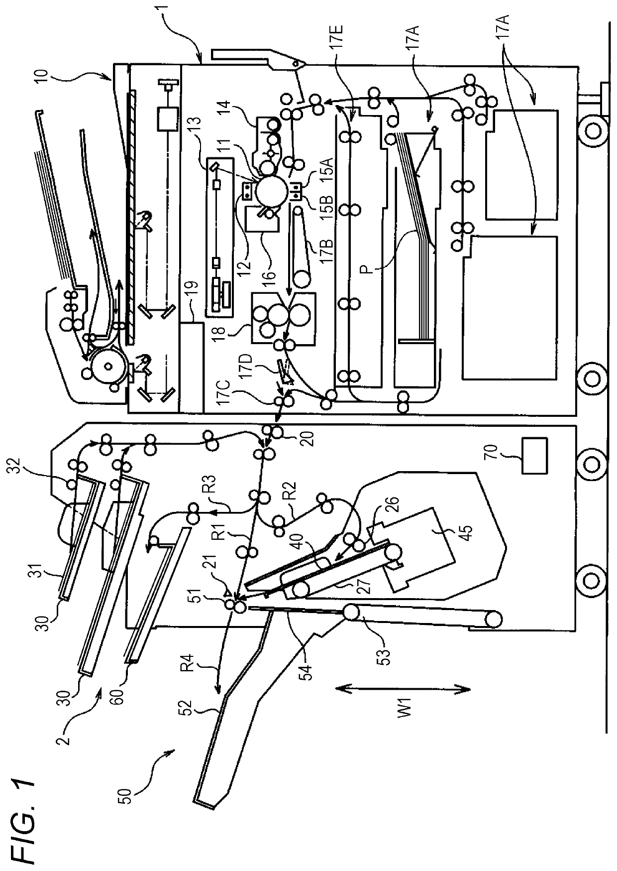
[0019]FIG. 1 is a configuration diagram schematically illustrating an image forming system according to the present embodiment. The image forming system according to the present embodiment includes an image forming apparatus 1 and a postprocessing apparatus 2.

[0020]The image forming apparatus 1 is an electrophotographic image forming system such as a copying machine, and the image forming apparatus 1 forms an image on paper P on the basis of image data. The image forming apparatus 1 includes an original reader 10, a photoreceptor 11, an electrifier 12, an image exposure unit 13, a developing unit 14, a transfer unit 15A, a separator 15B, a cleaning device 16, a fixing device 18, and an image formation controller 19.

[0021]The original reader 10 is disposed in an upper portion of a housing of the image forming apparatus 1, and includes an automatic original delivering unit that automatically moves an original in reading an image. This original reader 10 reads an image formed on the or...

second embodiment

[0084]An image forming system according to a second embodiment is described below. This image forming system according to the second embodiment is different from the image forming system according to the first embodiment in that the air volume of the blower fan 56 is controlled. A difference from the first embodiment is principally described below.

[0085]FIG. 8 is an explanatory diagram illustrating a relationship between information relating to paper P and the air volume of the blower fan 56. The basis weight of paper P is handled below at three levels, large, medium, and small. In addition, the air volume of the blower fan 56 is handled at three levels, large, medium, and small.

[0086]In a case where paper P has a large basis weight, the paper P tends to be easily deflected due to its own weight. Therefore, sticking onto uppermost paper P easily occurs. Accordingly, by selecting a large air volume, paper P supported by the paper floating members 57 can be caused to significantly flo...


PUM

PropertyMeasurementUnit
air volumeaaaaaaaaaa
widthaaaaaaaaaa
weightaaaaaaaaaa

Abstract

A paper stacking device includes: a stacker on which paper is stacked; a paper ejector that ejects the paper; an aligning plate that is provided on a side of the paper, and aligns a side end of the paper; a paper floating member that is provided in the aligning plate, and supports, from below, the side end of the paper; and a blower that is provided on the side of the paper across the aligning plate, and blows air, wherein the aligning plate includes a blowing opening through which air from the blower is blown, the paper floating member is switched between: a paper floating position; and a retreat position, when the paper floating member is located in the paper floating position, the blowing opening is opened, and when the paper floating member is located in the retreat position, the blowing opening is shielded.

Description

[0001]The entire disclosure of Japanese patent Application No. 2018-218547, filed on Nov. 21, 2018, is incorporated herein by reference in its entirety.BACKGROUNDTechnological Field[0002]The present invention relates to a paper stacking device and an image forming system.Description of the Related Art[0003]An image forming apparatus or a paper processing apparatus includes a paper stacking device that stacks paper on which prescribed processing has been performed. The paper stacking device includes an ejected paper tray (a stacker) on which paper is stacked, and a paper ejecting roller (a paper ejector) that ejects paper toward the ejected paper tray. The paper ejected from the paper ejecting roller is sequentially staked on the ejected paper tray. Meanwhile, in this type of paper stacking device, paper ejected from a paper ejecting roller is stuck onto paper stacked on an ejected paper tray, and in particular, uppermost paper, in some cases. In these cases, a front end of the eject...

Claims


Application Information

Patent Timeline
Patent Type & Authority Applications(United States)
IPC IPC(8): B65H31/26G03G15/00B65H29/24
CPCB65H29/246B65H2515/212G03G15/6552B65H31/26B65H2404/7414B65H2405/11425B65H2405/11151B65H2801/06B65H31/38B65H31/10B65H29/34B65H2511/214B65H2511/12B65H2515/10B65H2511/51B65H2601/273B65H2301/4461B65H2406/121G03G15/6573G03G21/206B65H2515/20B65H2220/02B65H2220/11B65H2220/01B65H2406/1211
Inventor TSUCHIYA, TSUYOSHI
Owner KONICA MINOLTA INC
Why Eureka
Try Eureka