Magneto-optical recording medium for use in domain wall displacement detection system, and method for producing the same

a technology of magnetic optical recording medium and domain wall displacement detection system, which is applied in the field of optical disks, can solve the problems of long initialization time and achieve the effect of high recording density

Inactive Publication Date: 2005-12-13
PANASONIC CORP
View PDF18 Cites 3 Cited by
  • Summary
  • Abstract
  • Description
  • Claims
  • Application Information

AI Technical Summary

Benefits of technology

[0009]Therefore, with the foregoing in mind, it is an object of the present invention to provide an optical disk having a high recording density, which can be initialized in a short period of time, and a method for producing the same.
[0010]In order to achieve the above-mentioned object, there is provided a method for producing an optical disk including a substrate and a recording layer disposed above the substrate and reproducing an information signal by a DWDD system, using light incident from the substrate side, the method including the processes of: (i) forming a first dielectric layer, the recording layer, and a second dielectric layer on the substrate in this order; and (ii) irradiating the recording layer with laser light for initialization from the second dielectric layer side, thereby weakening magnetic coupling of a part of the recording layer. According to the above-mentioned method for producing an optical disk, an optical disk can be produced with a high recording density and satisfactory productivity. In the present specification, the term “initialization” refers to a process of weakening magnetic coupling between recording tracks by annealing a part of the recording layer.

Problems solved by technology

Furthermore, for the same reason, it is difficult to enhance an absorption efficiency of the laser light 7 for annealing in the recording layer 4, so that initialization at a high linear velocity cannot be conducted, resulting in a long initialization time.

Method used


Image

  • Magneto-optical recording medium for use in domain wall displacement detection system, and method for producing the same
  • Magneto-optical recording medium for use in domain wall displacement detection system, and method for producing the same
  • Magneto-optical recording medium for use in domain wall displacement detection system, and method for producing the same

Examples


embodiment 1

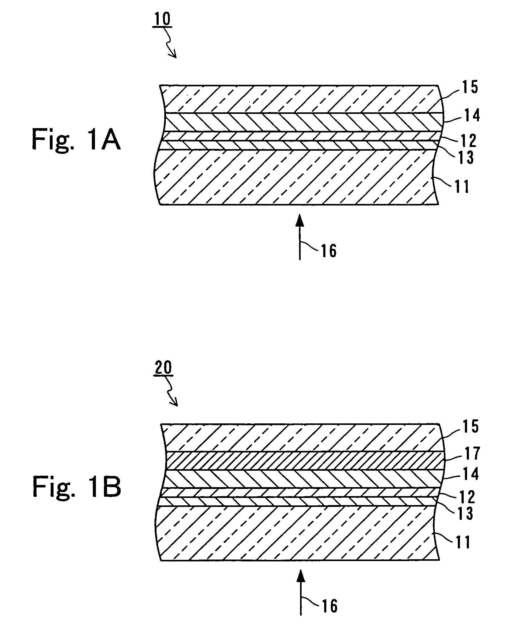
[0040]In Embodiment 1, an example of an optical disk of the present invention will be described. FIG. 1A is a partial cross-sectional view of an optical disk 10 of Embodiment 1.

[0041]Referring to FIG. 1A, an optical disk 10 includes a substrate 11, a recording layer 12 disposed above the substrate 11, a first dielectric layer 13 disposed between the substrate 11 and the recording layer 12, a second dielectric layer 14 disposed on the recording layer 12 opposite to the substrate 11, and a protective coating layer 15 disposed on the second dielectric layer 14. The optical disk 10 reproduces an information signal by using light 16 incident on the side of the substrate 11. In the recording layer 12, magnetic coupling is weakened partially by using light with a wavelength λ that is incident on the side of the second dielectric layer 14.

[0042]The substrate 11 has a disk shape. As a material for the substrate 11, for example, polycarbonate, glass, or the like can be used. The thickness of ...

embodiment 2

[0057]In Embodiment 2, an example of a method for producing an optical disk according to the present invention will be described. Embodiment 2 is directed to a method for producing an optical disk that reproduces an information signal by the DWDD system, using light incident on a substrate side. In Embodiment 2, the case will be described in which the optical disk 10 of Embodiment 1 is produced. Furthermore, the same components as those described in Embodiment 1 are denoted with the same reference numerals as those therein, and a repeated description thereof will be omitted herein (this also applies to the other embodiments).

[0058]According to the production method of Embodiment 2, the first dielectric layer 13, the recording layer 12, and the second dielectric layer 14 are formed on the substrate 11 in this order (hereinafter, this process may be referred to as “Process (i)”). These layers can be formed continuously by, for example, sputtering using a magnetron sputtering apparatus...

embodiment 3

[0071]In Embodiment 3, another exemplary method for producing an optical disk according to the present invention will be described. The production method of Embodiment 3 is different from that of Embodiment 2 only in the initialization process (Process (ii)). Therefore, a repeated description thereof will be omitted here.

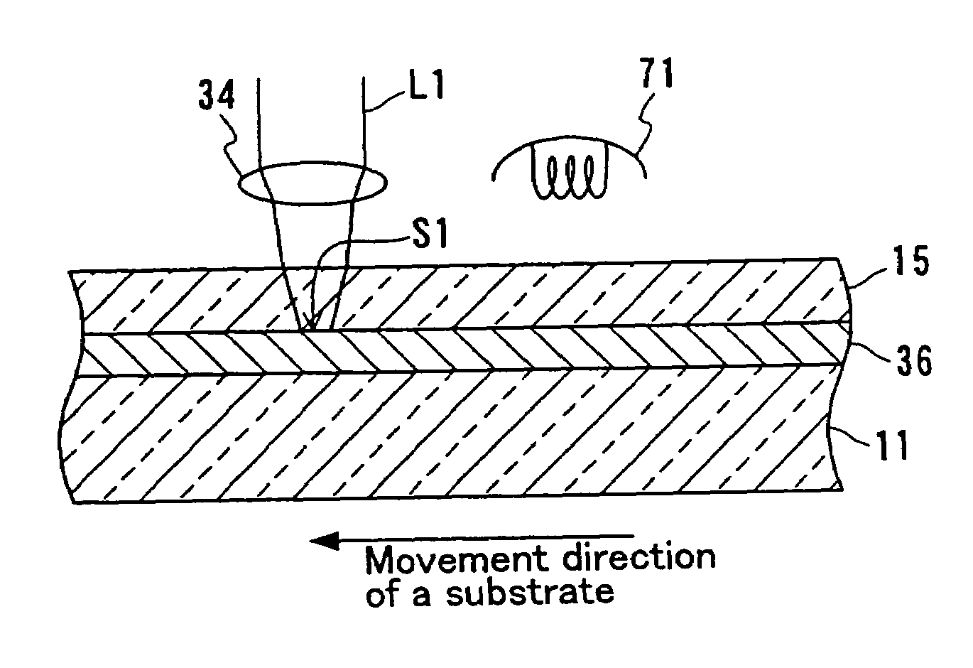
[0072]Hereinafter, the initialization method of Embodiment 3 will be described. FIG. 6 schematically shows a structure of an initialization apparatus 60 used by the production method of Embodiment 3.

[0073]Referring to FIG. 6, the initialization apparatus 60 includes a laser light source 31 for annealing, laser beam splitters 32, 62 and 65, a focus detector 33, an objective lens 34, a focus actuator 35, a laser light source 61 for tracking servo, a photodetector 63, and a tracking actuator 64.

[0074]An operation of the initialization apparatus 60 will be described with reference to FIG. 6. Laser light L2 emitted from the laser light source 61 passes through the beam s...


PUM

PropertyMeasurementUnit
thicknessaaaaaaaaaa
wavelengthaaaaaaaaaa
thicknessaaaaaaaaaa

Abstract

An optical disk of the present invention includes a substrate and a recording layer disposed above the substrate, and reproduces an information signal by a DWDD system, using light incident from the substrate side. The optical disk further includes a first dielectric layer disposed between the substrate and the recording layer and a second dielectric layer disposed on the recording layer opposite to the substrate, wherein the recording layer is initialized with light having a wavelength λ incident from the second dielectric layer side, and the thickness of the second dielectric layer is in a range of λ / (12×n) to λ / (2×n) (where n is a refractive index of the second dielectric layer).

Description

BACKGROUND OF THE INVENTION[0001]1. Field of the Invention[0002]The present invention relates to an optical disk used for recording / reproducing information and a method for producing the same.[0003]2. Description of the Related Art[0004]In the field of optical disks, there is a demand for high-density recording of information. As a method for realizing such high-density recording, a domain wall displacement detection (DWDD) system has been proposed.[0005]In an optical disk of the DWDD system, it is required to weaken magnetic coupling between adjacent recording tracks. Therefore, in the case of producing an optical disk of the DWDD system, initialization for weakening magnetic coupling between adjacent recording tracks is conducted before recording an information signal. Such an initialization method has been reported in the past (see JP 6(1994)-290496 A and JP10(1998)-340493 A).[0006]FIG. 10 shows an example of a structure and an initialization method of a conventional optical disk...

Claims


Application Information

Patent Timeline
Patent Type & Authority Patents(United States)
IPC IPC(8): B32B3/02G11B11/105
CPCB32B3/02G11B11/10578G11B11/10584G11B11/10582Y10T428/31G11B11/10586
Inventor UCHIDA, KIYOSHIHINO, YASUMORIMURAKAMI, MOTOYOSHIMIYATAKE, NORIO
Owner PANASONIC CORP
Why Eureka
Try Eureka