Valve piloting arrangements for hydraulic percussion devices

Pending Publication Date: 2020-05-28
MINCON INT
1 Cites 0 Cited by

AI-Extracted Technical Summary

Problems solved by technology

Percussion devices with valve piloting arrangements as described above in relation to FIGS. 1a to 1c and FIGS. 2a and 2b can suffer from substantial internal leakages.
In addition to the leakages at the piston undercut, there will also be leakages...

Benefits of technology

[0014]Typically, the rear end of the piston has a minimum piston diameter. The rear end of the piston typically also has the smallest running clearances. Because of the reduced piston diameter, the cylinder typically has an increased wall thickness in this region, so that the surrounding structure is stiffer. This means that the clearances tend to increase less under pressure. Furthermore, no dedicated seal drainage ports are required, as...

Abstract

A hydraulic percussion device comprising a piston mounted for reciprocal motion within a cylinder to impact a percussion bit and a control valve to control reciprocation of the piston. A valve pilot line is arranged to switch the control valve based on the position of the piston within the cylinder, wherein the valve pilot line is alternately connected, by the reciprocal movement of the piston, to high and low pressure lines (P, T) via an undercut in the piston. The undercut is located at a portion of the piston having a diameter less than the maximum sealing diameter of the piston.

Application Domain

Technology Topic

Image

  • Valve piloting arrangements for hydraulic percussion devices
  • Valve piloting arrangements for hydraulic percussion devices
  • Valve piloting arrangements for hydraulic percussion devices

Examples

  • Experimental program(1)

Example

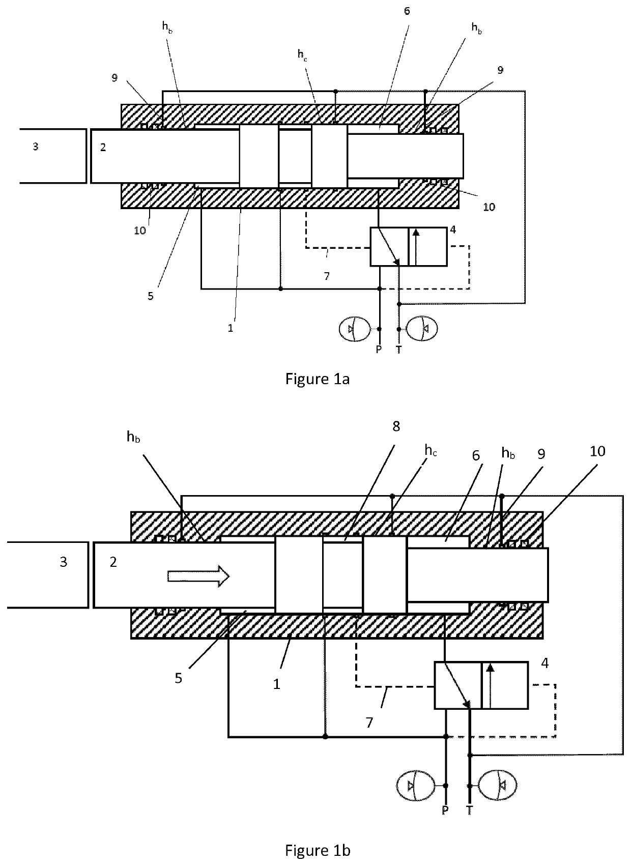
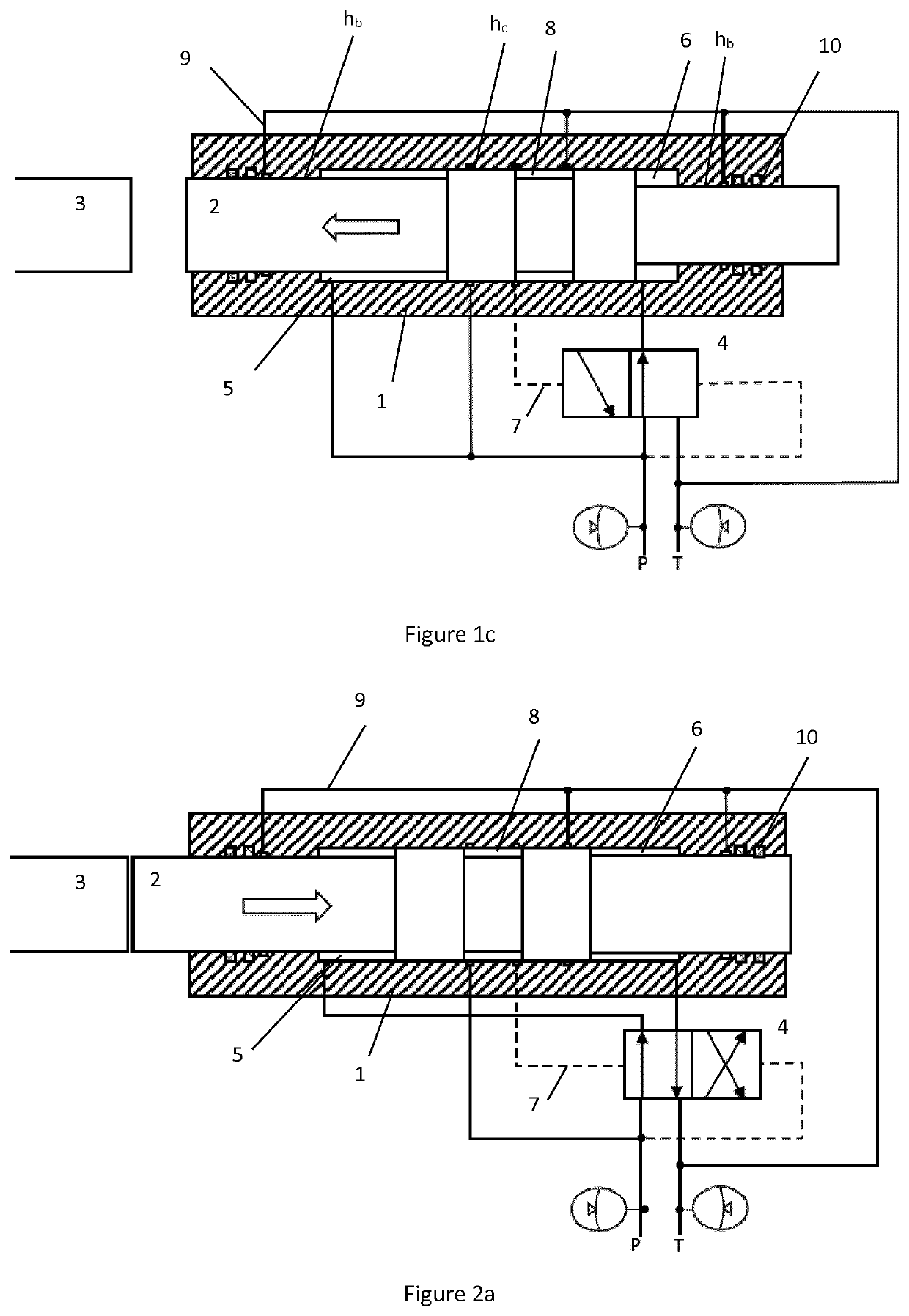
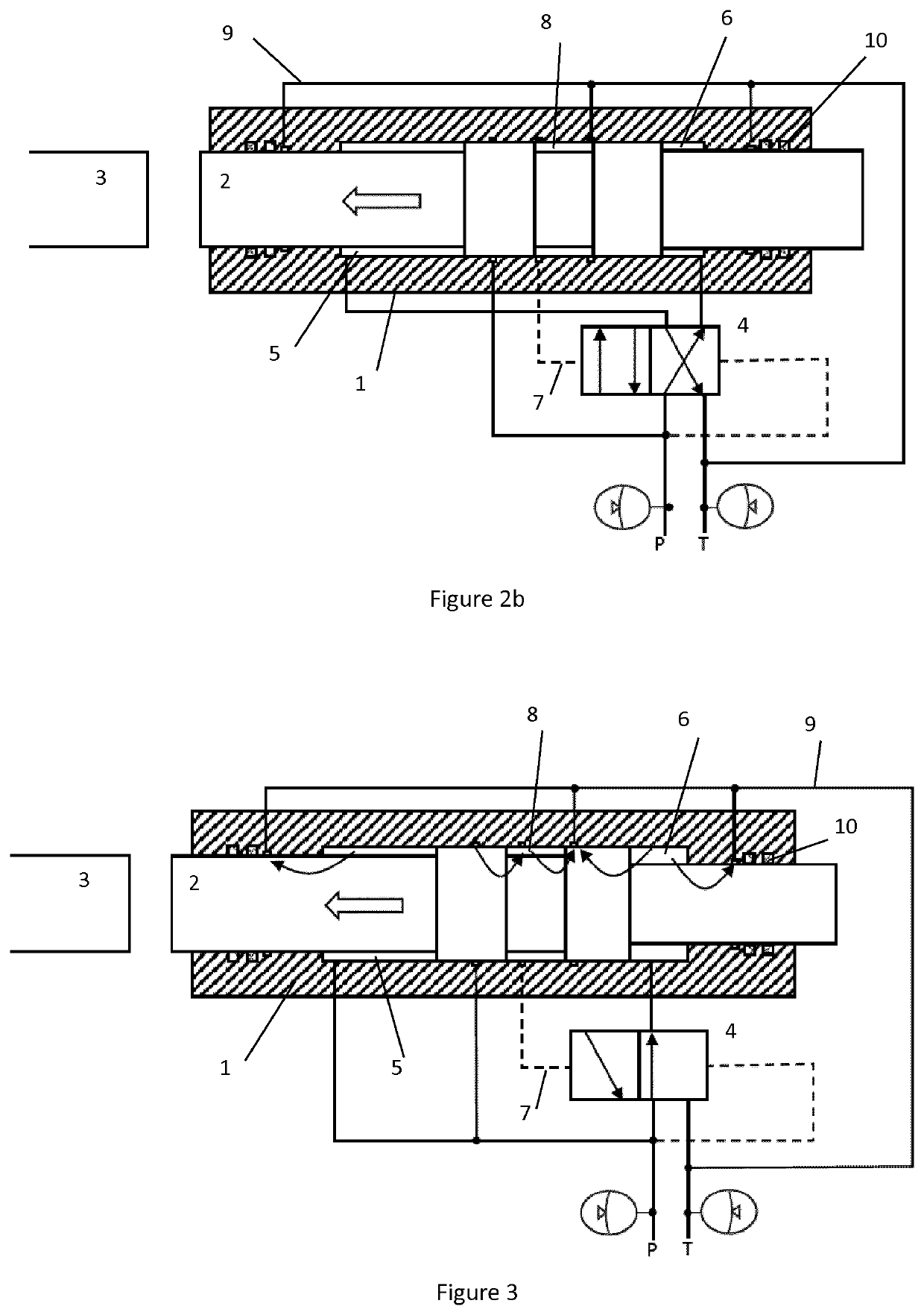
[0034]A third embodiment of the invention is illustrated in FIGS. 6a and 6b. In this embodiment, the undercut 208 is located at a forward end of the piston. As shown in FIGS. 6a and 6b, the undercut is located at a portion of the piston having a diameter D which is less than the maximum sealing diameter M of the piston. The valve pilot line 107 is connected between the left side 115 of the valve and the undercut 208 in the forward end of the piston 102. The right side of the valve 114 is connected to the high pressure line P by line 116.
[0035]FIG. 6a shows the device in a return stroke, where the piston is being driven away from the tool in the direction shown by the arrow. The valve pilot line 107 is connected to the low pressure line T via the undercut 208 in the forward end of the piston 102 and cylinder ports 120 and 121. Hydraulic forces acting on the valve have moved the valve to the left which in turn connects the rear chamber 106 with the low pressure line T. The front chamber 105 is continuously connected to high pressure so that the piston is driven away from the tool 103.
[0036]FIG. 6b shows the piston in a position in which the undercut 208 in the piston connects the valve pilot line 107 with the high pressure line P via cylinder port 120 and the front chamber, forcing the valve 104 to switch to the right position which in turn connects the rear chamber 106 with the high pressure line P. Since the piston area 112 of the rear chamber is greater than the piston area 113 of the front chamber, the net hydraulic force drives the piston towards the tool 103. Just before the piston impacts the tool, the valve pilot line is once again connected to the low pressure line and the control valve moves to the left to repeat the cycle.
[0037]Cylinder port 121 provides seal drainage for the forward seals 110, so that no dedicated seal drainage ports are required.
[0038]The words “comprises/comprising” and the words “having/including” when used herein with reference to the present invention are used to specify the presence of stated features, integers, steps or components but does not preclude the presence or addition of one or more other features, integers, steps, components or groups thereof.
[0039]It is appreciated that certain features of the invention, which are, for clarity, described in the context of separate embodiments, may also be provided in combination in a single embodiment. Conversely, various features of the invention which are, for brevity, described in the context of a single embodiment, may also be provided separately or in any suitable sub-combination.

PUM

no PUM

Description & Claims & Application Information

We can also present the details of the Description, Claims and Application information to help users get a comprehensive understanding of the technical details of the patent, such as background art, summary of invention, brief description of drawings, description of embodiments, and other original content. On the other hand, users can also determine the specific scope of protection of the technology through the list of claims; as well as understand the changes in the life cycle of the technology with the presentation of the patent timeline. Login to view more.

Similar technology patents

Image forming apparatus having detachable image bearing and transfer belt mechanisms

ActiveUS20210278784A1Increase wall thicknessIncreases thickness of frameElectrographic process apparatusStructural engineeringImaging equipment
Owner:FUJIFILM BUSINESS INNOVATION CORP

Optical imaging system and display device

PendingCN110764214AIncrease wall thicknessIncrease contact areaMountingsDisplay deviceMaterials science
Owner:ZHEJIANG SUNNY OPTICAL CO LTD

Access port

Owner:B BRAUN MEDICAL

Classification and recommendation of technical efficacy words

  • Increase wall thickness

Microcircuits for small engines

ActiveUS20070177976A1Increase wall thicknessEngine manufactureEngine fuctionsSmall engineTurbine
Owner:RAYTHEON TECH CORP

Microtitration plate

InactiveUS20050058578A1Low toleranceIncrease wall thicknessBioreactor/fermenter combinationsBiological substance pretreatmentsEngineeringOxygen
Owner:EPPENDORF AG

Balloon catheter having a balloon with a thickened wall portion

InactiveUS7011646B2Increase wall thicknessIncrease strength of balloonStentsBalloon catheterSecondary layerHigh intensity
Owner:ABBOTT CARDIOVASCULAR

Ribbed hose for milk extraction

ActiveUS20090217879A1More flexibility and bendabilityIncrease wall thicknessCathetersHeat exhanger conduitsEngineeringMechanical engineering
Owner:WEISEL BEVERLY SUE
Why Eureka
Try Eureka