Joint mobilization apparatus

a joint mobilization and apparatus technology, applied in the field of rehabilitation apparatus, can solve the problems of therapists' burden, high labor intensity and time consumption, and achieve the effect of facilitating patient use independently and reducing the burden of physical strength of therapists

Active Publication Date: 2020-06-04
ASIA UNIVERSITY
View PDF0 Cites 1 Cited by
  • Summary
  • Abstract
  • Description
  • Claims
  • Application Information

AI Technical Summary

Benefits of technology

[0004]An objective of the present invention is to provide a joint mobilization apparatus which is able to reduce a therapist's burden in physical strength, and facilitate a therapist and patient to operate independently.
[0006]The effect of the joint mobilization apparatus of the present invention is that the power unit can drive the pulling unit to pull reciprocatingly, to mobilize the patient's joint part, instead of therapist, so as to reduce the therapist's burden in physical strength and facilitate the patient to use independently.

Problems solved by technology

However, for the therapist, the implementation of joint mobilization is extremely labor-intensive and time-consuming; in recent years, the doctors to patient ratio is gradually increasing, so therapist often faces several patients in a day.
It is a great burden for the therapist, and the patient also has to rely on the therapist to rehabilitate and soothe the joints.

Method used


Image

  • Joint mobilization apparatus
  • Joint mobilization apparatus
  • Joint mobilization apparatus

Examples


first embodiment

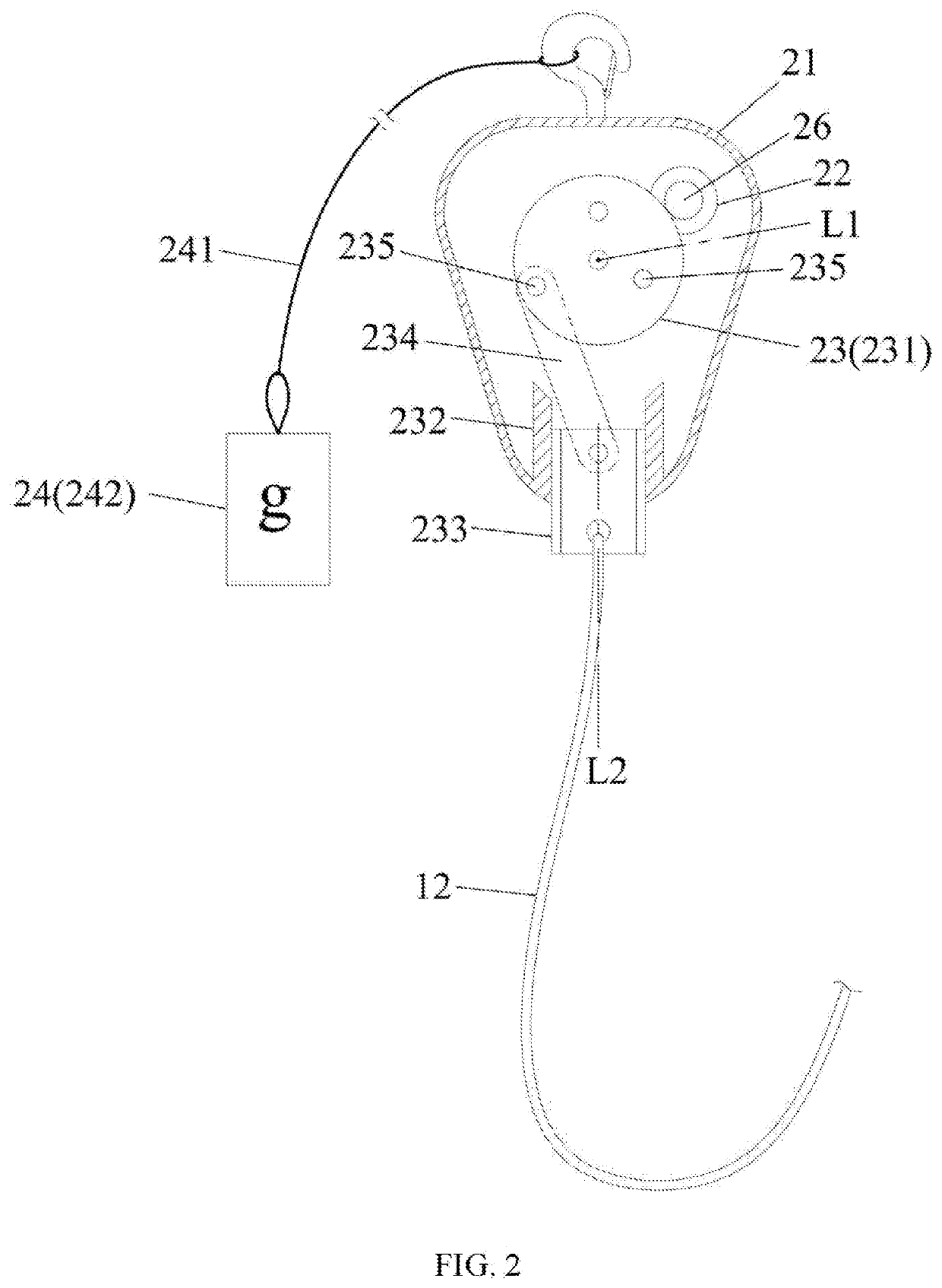
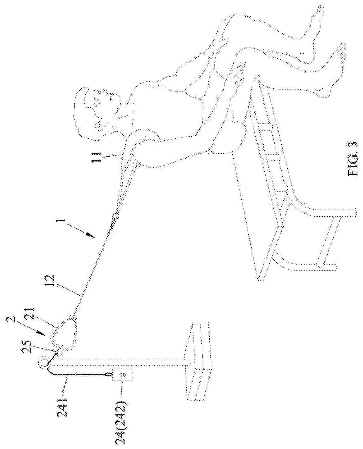
[0029]Please refer to FIGS. 1 and 2. a joint mobilization apparatus of the present invention comprises a pulling unit 1 and a power unit 2.

[0030]The pulling unit 1 comprises a wearable member set 11 and rope set 12. The wearable member set 11 is configured to mount on the patient's joint part, and the rope set 12 is connected to the wearable member set 11. In this embodiment, the rope set 12 has a rope 121 connected to the wearable member set 11 and the power unit 2.

[0031]The power unit 2 is configured to provide power of reciprocatingly pulling the rope set 12, the power unit 2 comprises a shell member 21, a motor 22 disposed on the shell member 21, a reciprocation mechanism 23 disposed on the shell member 21 and connected to the motor 22 and the rope set 12, a weight member set 24 detachably connected to the shell member 21, and a hook member 25 disposed on the shell member 21. The reciprocation mechanism 23 is driven by the motor 22 to reciprocate relative to the shell member 21,...

second embodiment

[0035]Please refer to FIGS. 6 and 10, which show a joint mobilization apparatus of the present invention applicable to mobilize the patient's shoulder joint, the joint mobilization apparatus comprises a base unit 3, a power unit 4, a pulling unit 5, a chair 6, and a turning unit 7.

[0036]Please refer to FIGS. 6 and 7. The base unit 3 comprises a base 31, a base frame 32 disposed on the base 31 and extended upwardly, two positioning member sets 33 respectively disposed on left and right sides of a top of the base frame 32, and two swingable arms 34 connected to the positioning member set 33 and respectively extended in directions away from the base frame. Each of the plurality of swingable arms 34 comprises a first end 341 connected to the positioning member set 33, and a second end 342 opposite to the first end 341. Relative to the positioning member set 33, the second end 342 is rotatable about the fourth axis IA which passes through the positioning member set 33 and is extended in ...


PUM


Abstract

A joint mobilization apparatus includes a pulling unit and a power unit. The pulling unit includes a wearable member set for mounting on the patient's joint part, and a rope set connected to the wearable member set. The power unit provides power of reciprocatingly pulling the rope set, and includes a shell member, a motor, and a reciprocation mechanism connected to the motor and the rope set. The reciprocation mechanism is driven by the motor to reciprocate relative to the shell member, so as to pull the rope set to reciprocate the wearable member set and patient's joint part. By using the power unit to drive the pulling unit to pull reciprocatingly for mobilizing the patient's joint part, instead of the therapist's treatment, the therapist's burden in physical strength can be reduced. Furthermore, the joint mobilization apparatus can provide the user to execute various muscle training modes.

Description

CROSS-REFERENCE TO RELATED APPLICATION[0001]This application claims priority from Taiwan Patent Application No. 107142711, filed on Nov. 29, 2018, in the Taiwan Intellectual Property Office, the content of which is hereby incorporated by reference in its entirety for all purposes.BACKGROUND OF THE INVENTION1. Field of the Invention[0002]The present invention relates to a rehabilitation apparatus, more particularly to a joint mobilization apparatus.2. Description of the Related Art[0003]Joint mobilization is a commonly used rehabilitation technique, which is performed by a therapist to manually position and apply the joints and related limbs of the patient to separate and pull the joint in a specific direction, so as to improve joint mobility, relieve pain and restore joint function. However, for the therapist, the implementation of joint mobilization is extremely labor-intensive and time-consuming; in recent years, the doctors to patient ratio is gradually increasing, so therapist o...

Claims


Application Information

Patent Timeline
Patent Type & Authority Applications(United States)
IPC IPC(8): A61H1/02
CPCA61H1/0218A61H2201/164A61H2201/1666A61H2201/1676A61H2201/1669A61H1/0281A61H2201/165A61H2201/1253A61H2201/1215A61H2201/1633A61H1/024A61H1/0274A61H2201/1638A61H2201/1642A61H2201/1664A61H2201/0119A61H2201/0149A61H2201/1436A61H2201/149A61H2203/0431A61H2203/0456
Inventor LEE, SHIN-DAWU, CHENG-JUHSU, WEI-CHUNYEH, HONG-JUN
Owner ASIA UNIVERSITY
Why Eureka
Try Eureka