Eureka AIR delivers breakthrough ideas for toughest innovation challenges, trusted by R&D personnel around the world.

Spindle locking apparatus for a rotary power tool

Active Publication Date: 2020-06-04
G A W INC
View PDF5 Cites 0 Cited by
  • Summary
  • Abstract
  • Description
  • Claims
  • Application Information

AI Technical Summary

Benefits of technology

The present invention is an improved spindle locking apparatus that can be used in both retrofit and OEM applications. It includes a locking sleeve, a locking collar, and drive pins that mechanically connect the collar to the sleeve. The locking sleeve is designed to lockingly engage the flat-sided portion of the spindle. The apparatus is easy to install and can be joined with a two-piece split ring and a spring steel clamp. The technical effect of this invention is to provide a reliable and secure spindle locking mechanism for power tools.

Problems solved by technology

Such locking mechanisms are typically designed into the power tool as an OEM (original equipment manufacturer) feature, and are not readily adaptable for retrofitting an existing power tool.

Method used


Image

  • Spindle locking apparatus for a rotary power tool
  • Spindle locking apparatus for a rotary power tool
  • Spindle locking apparatus for a rotary power tool

Examples


Embodiment Construction

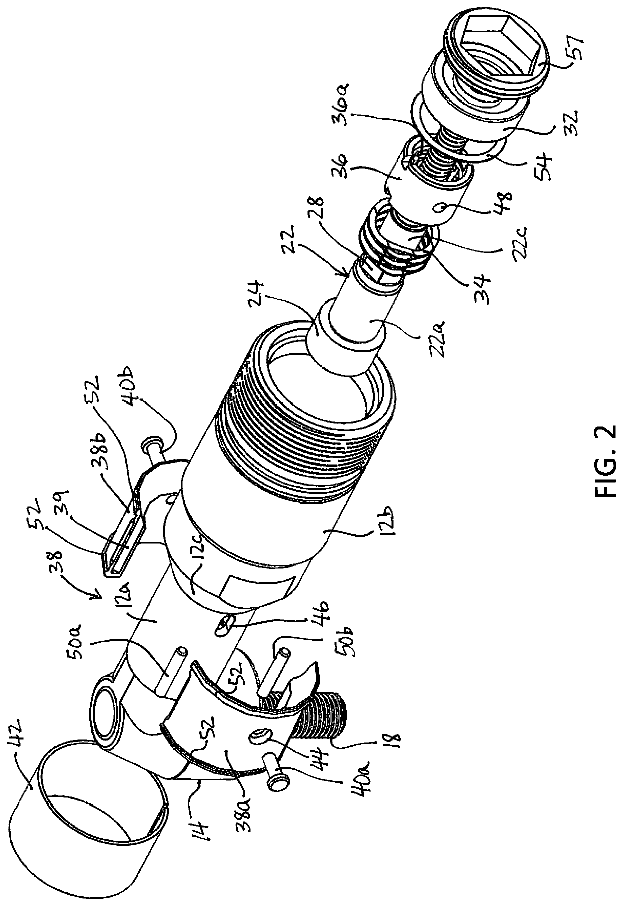
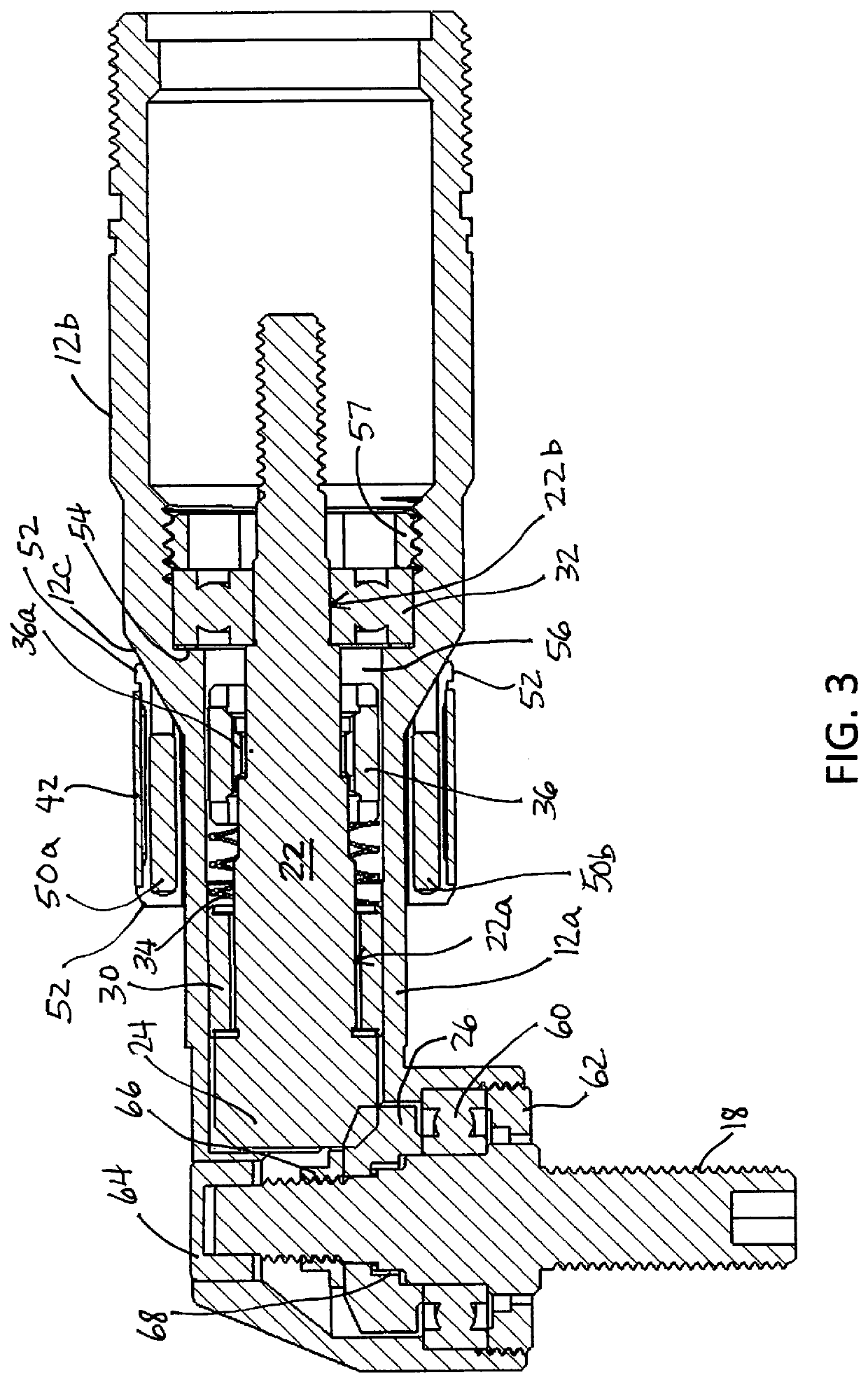
[0009]The spindle locking apparatus of this invention is designed for use in power tools having a spindle mounted for rotation within a tubular housing, where it is desirable to temporarily prevent the spindle from rotating with respect to the housing while attaching or removing implements driven by the spindle. One such power tool is an angle grinder having a threaded drive shaft, where abrasive grinding or cutting disks are secured to the drive shaft with a threaded fastener; in such tools, the spindle is mechanically coupled to the drive shaft, and it is desirable to rotationally lock the spindle (and drive shaft) when attaching or removing the threaded fastener.

[0010]The locking apparatus of the present invention is illustrated herein in the context of an angle grinder, and the angle grinder's front housing assembly 10 is shown in the drawings. Referring to FIGS. 1-2, the front housing assembly 10 includes a tubular housing 12 and hub 14 (which are mechanically joined, or formed...


PUM


Abstract

A spindle locking apparatus for power tools having a spindle mounted for rotation within a tubular housing. The locking apparatus includes a locking sleeve disposed between the spindle and its tubular housing, a locking collar surrounding the tubular housing radially outboard of the locking sleeve, and a set of drive pins mechanically coupling the locking collar to the locking sleeve through axial slots in the tubular collar. The inner periphery of the locking sleeve is shaped to lockingly engage a flat-sided portion of the spindle, and a spring element biases the locking sleeve away from the flat-sided portion of the spindle to unlock the spindle. The locking collar is axially shiftable against the spring bias as permitted by the slots in the tubular housing to bring the locking sleeve into locking engagement with the flat-sided portion of the spindle to prevent spindle rotation.

Description

TECHNICAL FIELD[0001]This invention relates to power tools having a rotary spindle or shaft, and more particularly to a user-manipulated spindle locking apparatus for selectively preventing spindle rotation.BACKGROUND OF THE INVENTION[0002]Rotary power tools, particularly those incorporating a collet for securing a drill bit or other rotary bit, will frequently incorporate a drive shaft locking apparatus to enable a user to tighten or loosen the collet without also turning the drive shaft; see, for example, the U.S. Patent No. 5,496,139 to Ghode et al. Although less commonly, similar locking mechanisms can also be used in connection with angle grinders, routers, and other rotary power tools to enable a user to remove or install an implement such as a grinder wheel or router blade without also turning the spindle. Such locking mechanisms are typically designed into the power tool as an OEM (original equipment manufacturer) feature, and are not readily adaptable for retrofitting an ex...

Claims


Application Information

Patent Timeline
IPC IPC(8): B23Q11/00B25F5/00B25B33/00
CPCB25B33/005B25F5/001B23Q11/0092B25B21/00
Inventor ARTHUR, ROBERTWENZEL, NATHANIEL PRUSSELL, NICHOLAS JFLAHERTY, MICHAEL J
Owner G A W INC
Why Eureka
Eureka Blog
Learn More