
Air purification device

a technology of air purification device and adsorption block, which is applied in the direction of dispersed particle separation, transportation and packaging, and separation processes, etc., can solve the problems of difficult to sufficiently disperse the purification target substances and achieve the reduction of thermal conduction from the adsorption block to the housing through the support protrusion, and the effect of sufficient support rigidity

Active Publication Date: 2020-06-04
HONDA MOTOR CO LTD
View PDF0 Cites 2 Cited by
  • Summary
  • Abstract
  • Description
  • Claims
  • Application Information

AI Technical Summary

Benefits of technology

The present invention provides an air purification device that can efficiently disperse purification target substances during regeneration of the adsorption block. The device has a hollow chamber that provides excellent insulating properties and allows smooth expansion of the outer surface of the adsorption block due to heat. This minimizes application of an unnecessary external force to surroundings due to thermal expansion of the outer surface of the adsorption block. The device also has a support protrusion with a hemi-spherical tip that provides sufficient support rigidity with respect to the adsorption block and reduces thermal conduction from the adsorption block to the housing. An insulating layer is provided between the housing and the outer surface of the adsorption block, minimizing heat transfer from the adsorption block to the housing and making it difficult for heat to be radiated from the adsorption block to the outside. This allows for efficient dispersal of purification target substances during regeneration of the adsorption block.

Problems solved by technology

For this reason, when the output of the device configured to heat air is not increased, it is difficult to sufficiently disperse the purification target substances from the adsorption block.

Method used


Image

  • Air purification device
  • Air purification device
  • Air purification device

Examples


Embodiment Construction

[0028]Hereinafter, embodiments of the present invention will be described with reference to the accompanying drawings.

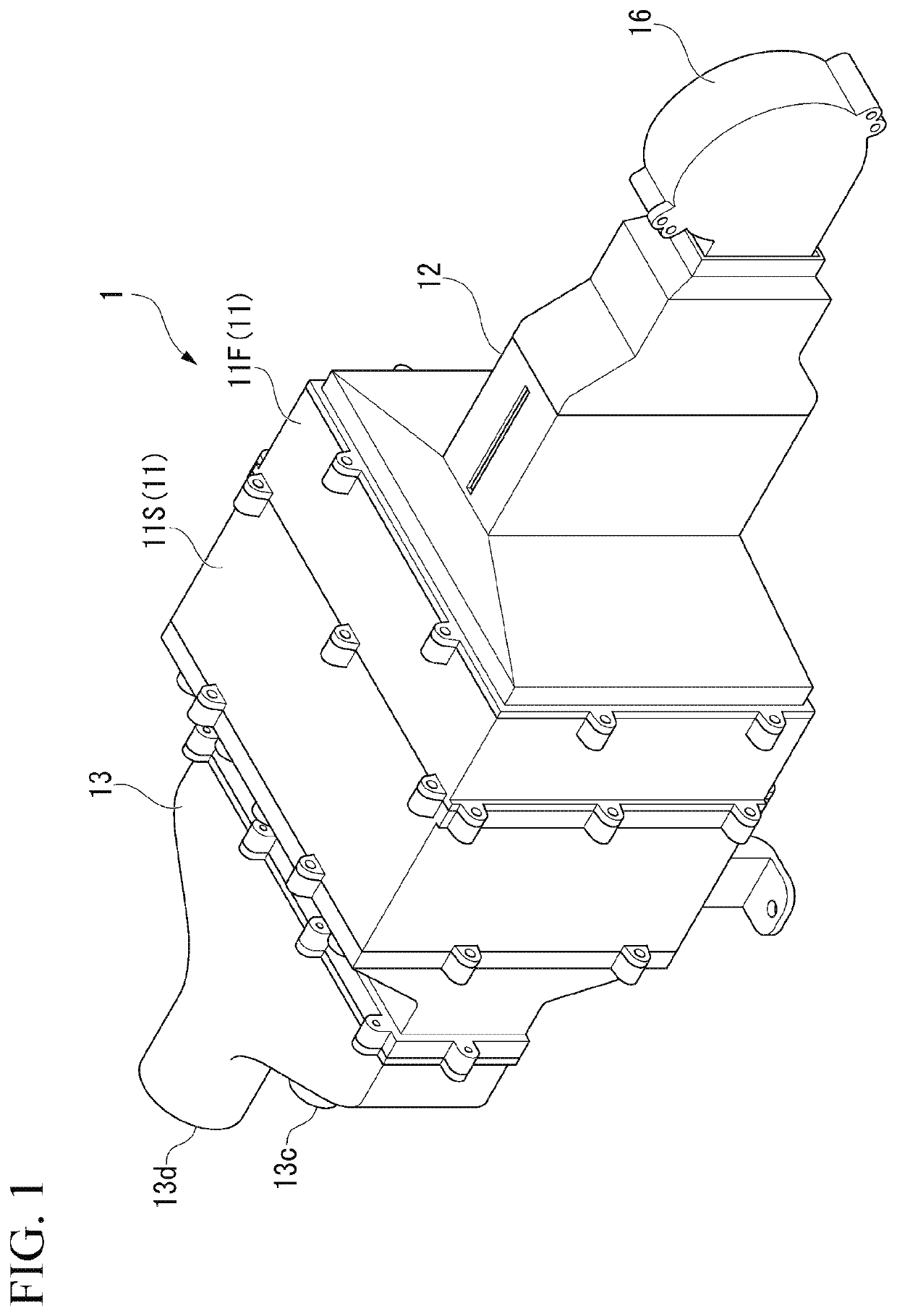
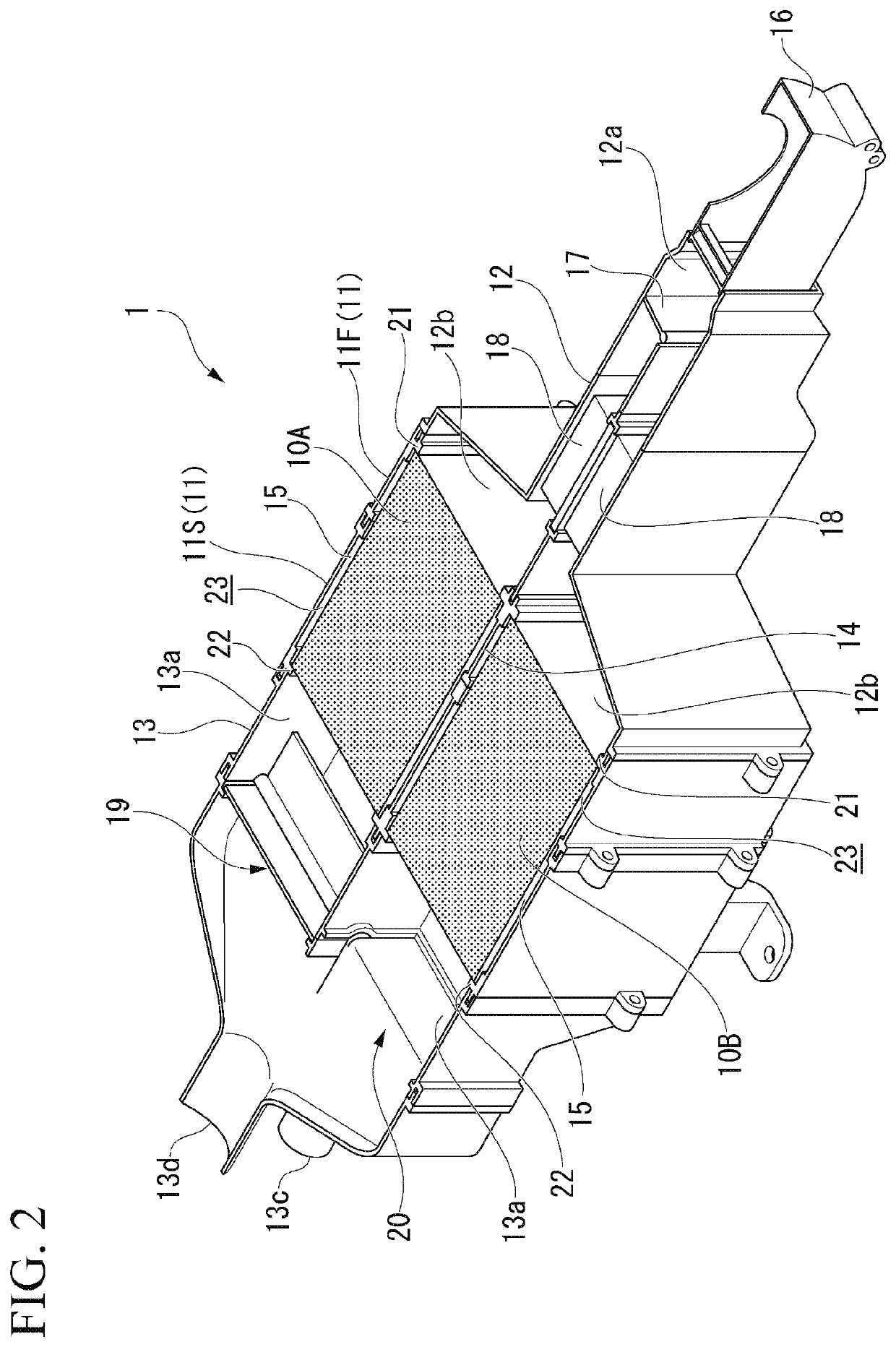
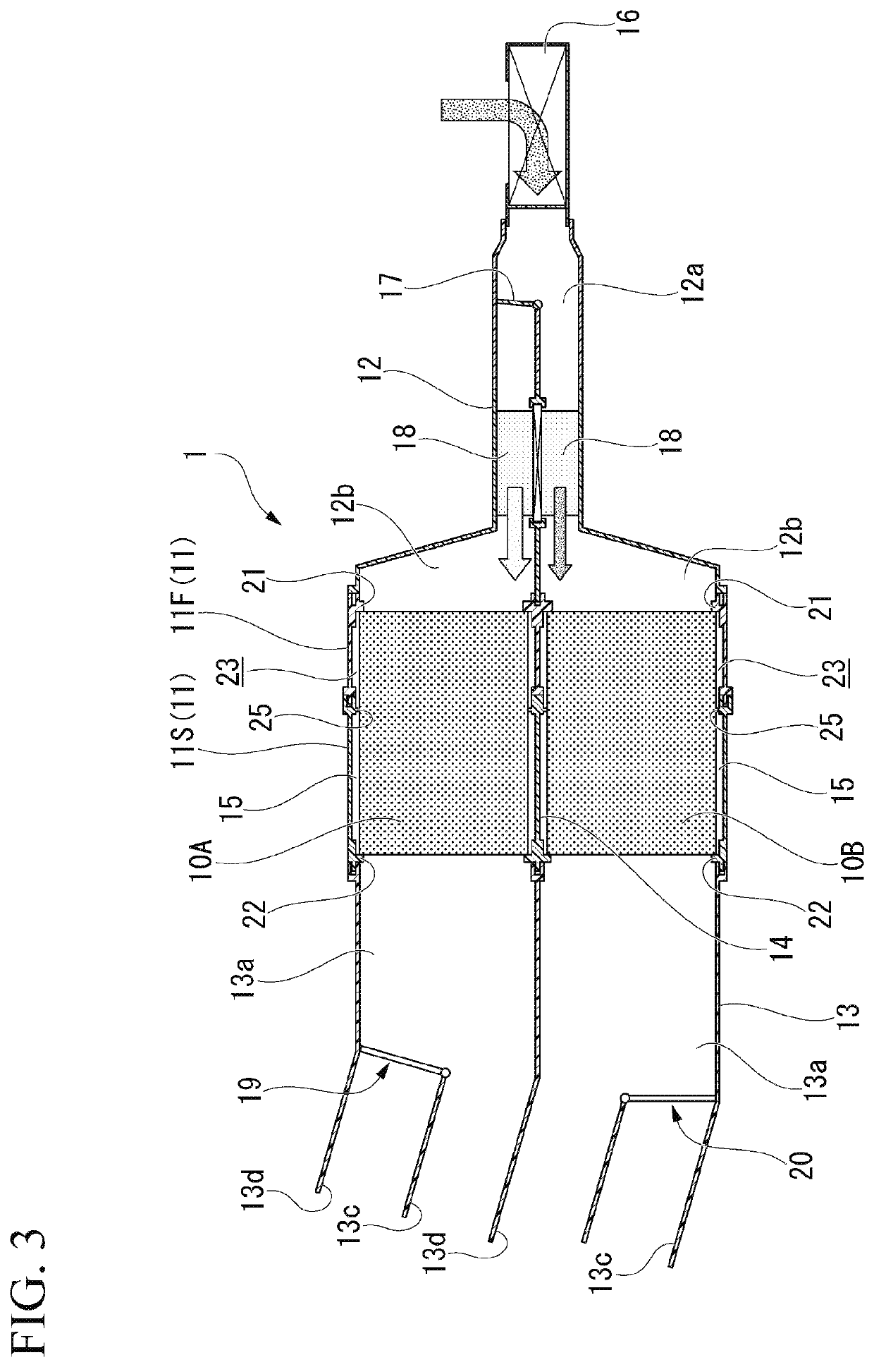
[0029]FIG. 1 is a perspective view of an air purification device 1 of the embodiment, and FIG. 2 is a partially cutout perspective view showing the air purification device 1 in FIG. 1, of which a substantially upper half section is cut out. In addition, FIG. 3 is a schematic cross-sectional view of the air purification device 1 showing an internal structure of the air purification device 1.

[0030]The air purification device 1 of the embodiment is a purification device configured to purify air in a passenger compartment of a vehicle, and at least carbon dioxide and water vapor in the passenger compartment can be removed. The air purification device 1 includes a pair of adsorption blocks 10A and 10B configured to cause air to circulate through the passenger compartment and adsorb purification target substances in air, a rectangular tubular housing 11 configured to accom...


PUM


Abstract

An air purification device includes an adsorption block, a housing, an introduction port for indoor air, an introduction port for heated air, a return port for indoor air, and a discharge port for used regeneration air. The adsorption block adsorbs purification target substances in indoor air, and is regenerated by dispersing the adsorbed purification target substances by circulating heated air. The housing accommodates the adsorption block therein. The introduction port for indoor air and the introduction port for heated air are provided on one end side of the housing. The return port for indoor air and the discharge port for used regeneration air are provided on the other end side of the housing. An insulating layer is provided between the housing and an outer surface of the adsorption block.

Description

CROSS-REFERENCE TO RELATED APPLICATION[0001]Priority is claimed on Japanese Patent Application No. 2018-225473, filed Nov. 30, 2018, the content of which is incorporated herein by reference.BACKGROUND OF THE INVENTIONField of the Invention[0002]The present invention relates to an air purification device configured to adsorb purification target substances indoors and purify indoor air.Description of Related Art[0003]As an air purification device used in a vehicle or the like, a device configured to adsorb purification target substances in the interior using an adsorption block that supports an adsorbent such as activated carbon or the like is known. The air purification device is configured to take the air in the interior into a casing, and return purified air after the purification target substances in the air have been adsorbed by the adsorption block to the interior.[0004]In the adsorption block disposed in the casing, the concentration of the purification target substances adsorb...

Claims


Application Information

Patent Timeline
IPC IPC(8): B60H3/06B01D53/04
CPCB60H2003/0691B01D2259/402B01D53/0446B60H3/0633B01D2259/40086B60H3/0641B01D2259/4566B60H3/06B01D53/04B60H3/0085B01D2258/06B01D2257/504B01D2257/80B01D53/0407Y02C20/40
Inventor MATSUMOTO, SUBARUKAKIZAKI, SHINJI
Owner HONDA MOTOR CO LTD
Learn More