Method and apparatus for transmitting and receiving signal based on beamforming in communication system

a technology of beamforming and communication system, applied in diversity/multi-antenna system, transmission path division, site diversity, etc., can solve the problems of low implementation complexity, large propagation loss in high frequency band, and inability to realize high resolution of analog beamforming, so as to improve communication system performance and reduce the load of signal for cooperative communication

Active Publication Date: 2020-06-04
ELECTRONICS & TELECOMM RES INST
View PDF26 Cites 3 Cited by
  • Summary
  • Abstract
  • Description
  • Claims
  • Application Information

AI Technical Summary

Benefits of technology

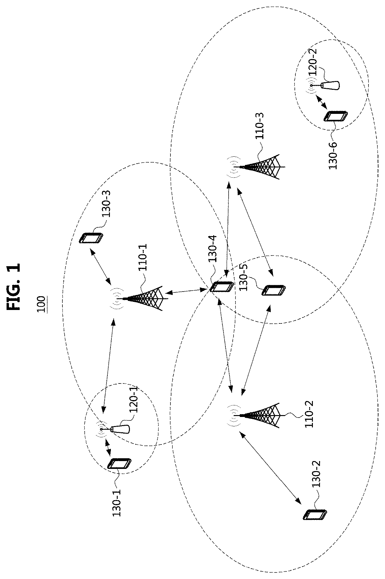
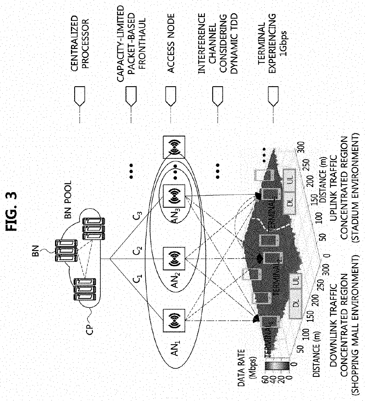
[0029]According to the present disclosure, in the ultra-dense network (UDN), a network cluster may be configured based on capability information of the terminal, and in the network cluster, a user cluster may be configured based on measurement information of a beamformed sounding reference signal (SRS) from the terminal. The user cluster may be configured with a plurality of access nodes (AN), states of uplink channels between the plurality of ANs belonging to the user cluster and the terminal may be measured based on the beamformed SRS from the terminal, and states of downlink channels between the plurality of ANs belonging to the user cluster and the terminal may be measured based on beamformed channel state information-reference signals (CSI-RSs) from the plurality of ANs. The cooperative communication between the plurality of ANs belonging to the user cluster and the terminal may be performed based on the measurement information of the uplink / downlink channel states. Accordingly, signaling load for the cooperative communication can be reduced, and the performance of the communication system can be improved.

Problems solved by technology

In general, since the diffraction and reflection characteristics of the radio waves in a high frequency band are not good, the propagation loss (e.g., path loss and reflection loss) in a high frequency band may be larger than the propagation loss in a low frequency band.
Although the complexity of implementing the analog beamforming is not high, the analog beamforming may not realize high resolution.
The digital beamforming may implement high resolution, but cost and complexity may increase because an antenna-specific radio frequency (RF) chain is required.

Method used


Image

  • Method and apparatus for transmitting and receiving signal based on beamforming in communication system
  • Method and apparatus for transmitting and receiving signal based on beamforming in communication system
  • Method and apparatus for transmitting and receiving signal based on beamforming in communication system

Examples


Embodiment Construction

[0057]Embodiments of the present disclosure are disclosed herein. However, specific structural and functional details disclosed herein are merely representative for purposes of describing embodiments of the present disclosure. Thus, embodiments of the present disclosure may be embodied in many alternate forms and should not be construed as limited to embodiments of the present disclosure set forth herein.

[0058]Accordingly, while the present disclosure is capable of various modifications and alternative forms, specific embodiments thereof are shown by way of example in the drawings and will herein be described in detail. It should be understood, however, that there is no intent to limit the present disclosure to the particular forms disclosed, but on the contrary, the present disclosure is to cover all modifications, equivalents, and alternatives falling within the spirit and scope of the present disclosure. Like numbers refer to like elements throughout the description of the figure...


PUM


Abstract

Disclosed are methods for transmitting and receiving beamforming-based signals in a communication system. An operation method of a terminal may comprise transmitting capability information of the terminal to an AN; receiving first configuration information of a network cluster configured based on the capability information from the AN; transmitting an SRS in a beamforming scheme through resources indicated by the first configuration information; receiving second configuration information of a user cluster configured based on a measurement result of the SRS from the AN; and performing cooperative communication with ANs belonging to the user cluster, which are indicated by the second configuration information. Accordingly, the performance of the communication system can be improved.

Description

CROSS-REFERENCE TO RELATED APPLICATIONS[0001]This application claims priority to Korean Patent Applications No. 10-2018-0151138, filed on Nov. 29, 2018, and No. 10-2019-0148033, filed on Nov. 18, 2019 with the Korean Intellectual Property Office (KIPO), the entire contents of which are hereby incorporated by reference.BACKGROUND1. Technical Field[0002]The present disclosure relates technologies for transmitting and receiving signals in a communication system, and more specifically, to technologies for transmitting and receiving signals by using hybrid beamforming.2. Related Art[0003]The communication system (hereinafter, a New Radio (NR) communication system) using a higher frequency band (e.g., a frequency band of 6 GHz or higher) than a frequency band (e.g., a frequency band of 6 GHz or lower) of the Long Term Evolution (LTE) (or, LTE-A) is being considered for processing of soaring wireless data. The NR communication system may support not only a frequency band below 6 GHz but al...

Claims


Application Information

Patent Timeline
Patent Type & Authority Applications(United States)
IPC IPC(8): H04B7/024H04B7/06H04L5/00H04B7/08
CPCH04L5/0007H04B7/024H04L5/0035H04L5/0048H04B7/088H04B7/0628H04B7/0695H04L5/0025H04L5/0051H04L5/0094
Inventor KIM, MIN HYUNNOH, TAE GYUNCHOI, IN KYEONGHONG, SEUNG EUN
Owner ELECTRONICS & TELECOMM RES INST
Why Eureka
Try Eureka