
Analyte detection system and method

Active Publication Date: 2020-06-11
SIEMENS HEALTHINEERS NEDERLAND BV
View PDF2 Cites 0 Cited by
  • Summary
  • Abstract
  • Description
  • Claims
  • Application Information

AI Technical Summary

Benefits of technology

The present invention provides a system and method for detecting a specific substance in a sample without needing to calibrate the system. The system includes a measurement chamber that holds a sample, an activator that interacts with the substance of interest, a heating element to control the temperature of the sample, and a sensor to detect the interaction between the substance of interest and the activator. By controlling the amount of activator and the temperature, the system can determine the concentration of the substance of interest in the sample based on the interaction kinetics between the substance of interest and the activator. This is particularly useful for substances that are abundant in the sample but in low concentrations. The system can provide a faster measurement result and can be easily operated without requiring a calibration.

Problems solved by technology

However, this requires substantial processing power, which may be undesirable from a cost perspective.
What is more, the need to perform multiple measurements before the amount of binding of a particular analyte can be determined means that the measurement result may not be quickly available, which is also disadvantageous.

Method used


Image

  • Analyte detection system and method
  • Analyte detection system and method
  • Analyte detection system and method

Examples


Embodiment Construction

[0032]It should be understood that the Figures are merely schematic and are not drawn to scale. It should also be understood that the same reference numerals are used throughout the Figures to indicate the same or similar parts.

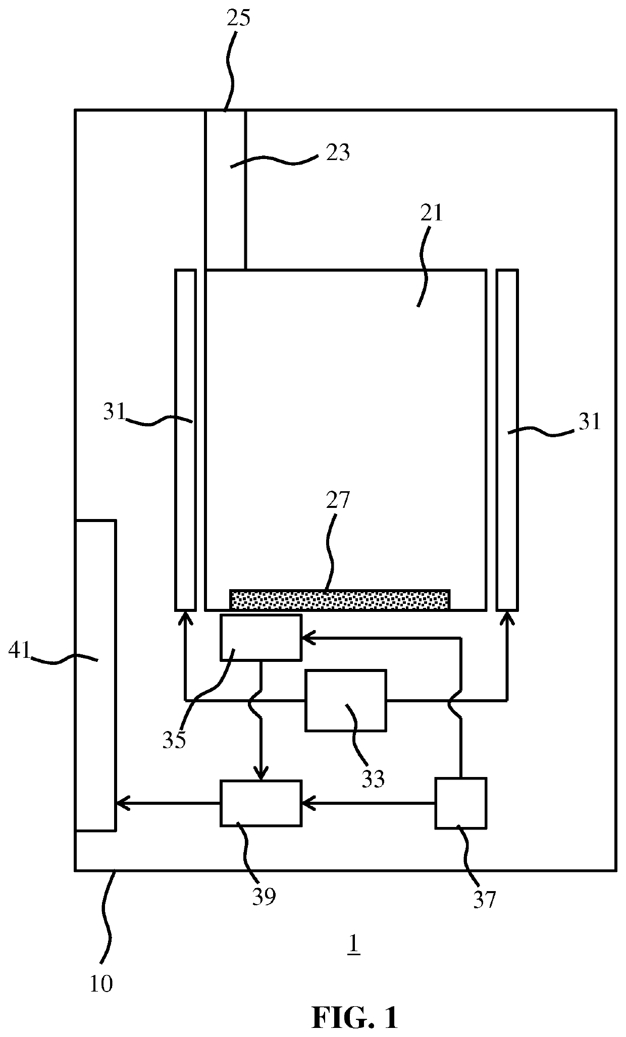
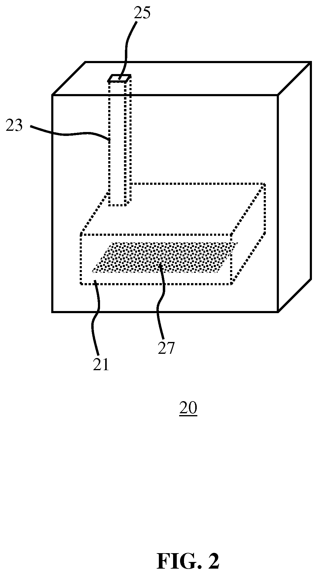
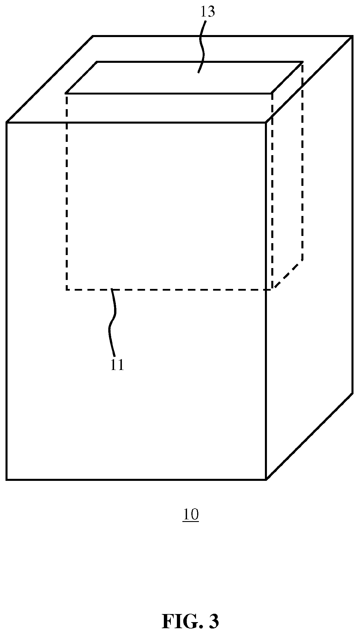
[0033]FIG. 1 schematically depicts a system 1 for detecting an analyte of interest in a sample according to an embodiment. The system 1 comprises an analysis unit 10 and a measurement chamber 21, which may be an integral part of the analysis unit 10 or may be provided as a separate entity to be inserted into the analysis unit 10 as will be explained in more detail below. The measurement chamber 21 typically has a well-defined volume such that upon filling of the measurement chamber 21 with a sample potentially including an analyte of interest, the measurement chamber 21 comprises a metered volume of the sample, i.e. a volume corresponding to the volume of the measurement chamber 21. The sample may be inserted into the measurement chamber 21 through an opening...


PUM


Abstract

A system (1) for detecting an analyte of interest in a sample is disclosed that comprises a measurement chamber (21) for metering the sample and including a defined concentration of an activator (27) causing the generation of a product when interacting with the analyte of interest, a heating element (31) thermally coupled to the measurement chamber, a controller (33) adapted to control the heating element such that the measurement chamber is maintained at a defined temperature (Td), a sensor (35) adapted to detect said product, a timer (37) adapted to time an interaction time between the sample and the activator; and a processor (39) responsive to the sensor and the timer. The processor is adapted to, upon addition of the sample to the measurement chamber, determine an amount of the analyte of interest in the sample from a sensor signal indicative of an amount of said product in the measurement chamber provided by the sensor prior to termination of said interaction; known interaction kinetics between the analyte of interest and the activator at the defined temperature and the defined concentration; and the interaction time at time of generation of the sensor signal. A method of detecting an analyte of interest in a sample using such a system is also disclosed.

Description

FIELD OF THE INVENTION[0001]The present invention relates to a system for detecting an analyte of interest in a sample.[0002]The present invention further relates to a method of detecting an analyte of interest in a sample with such a system.BACKGROUND OF THE INVENTION[0003]Point of care diagnostics is a rapidly growing area of medicine. The provision of diagnostic tools at the point of care allows for a rapid determination of data that can be used for diagnostic purposes, e.g. data of intermediate diagnostic relevance, in many cases without the need of the presence of a medical professional. Such diagnostic tools for example may be provided in the form of (disposable) assays, in which a user may insert a sample into a measurement chamber for the detection of (a concentration of) an analyte of interest in the sample using some binding agent or reagent. An example of such a diagnostic tool is an enzyme-linked immunosorbent assay, which may be used to detect the presence of an antigen...

Claims


Application Information

Patent Timeline
IPC IPC(8): G01N35/00
CPCG01N2035/00346G01N2035/0097G01N35/00584G01N33/52G01N33/5302G01N33/54366
Inventor NIEUWENHUIS, JEROEN HANSVAN ROOSMALEN, MARKUS HENDRIKUSVENGE, PER
Owner SIEMENS HEALTHINEERS NEDERLAND BV
Learn More