Ground electrode formed in an electrostatic chuck for a plasma processing chamber

a plasma processing chamber and ground electrode technology, applied in the direction of electrical equipment, basic electric elements, electric discharge tubes, etc., can solve the problems of non-uniformity or skew of processing

Active Publication Date: 2020-06-11
APPLIED MATERIALS INC
View PDF0 Cites 126 Cited by
  • Summary
  • Abstract
  • Description
  • Claims
  • Application Information

AI Technical Summary

Benefits of technology

[0007]Disclosed herein is a method for forming an electrostatic chuck (ESC). The method begins by sintering an aluminum nitride (AlN) or aluminum oxide body having a heater, an RF electrode mesh and a high voltage (HV) ESC electrode mesh. A ground electrode mesh is disposed along one or more outer surfaces of the sintered AlN body. The ground electrode mesh and the sintered body is encased in an aluminum powder to form an ESC body. The ESC body is sintered to form the ESC.

Problems solved by technology

Non-uniformity or skew of processing results (e.g., etch, deposition and the like) may be caused by asymmetry of the RF return path due bad or a broken ground.
However, the vertical wall of the substrate support is largely left without a proper ground which in term may promote the formation of parasitic plasma below the support surface of the substrate support.

Method used


Image

  • Ground electrode formed in an electrostatic chuck for a plasma processing chamber
  • Ground electrode formed in an electrostatic chuck for a plasma processing chamber
  • Ground electrode formed in an electrostatic chuck for a plasma processing chamber

Examples


second embodiment

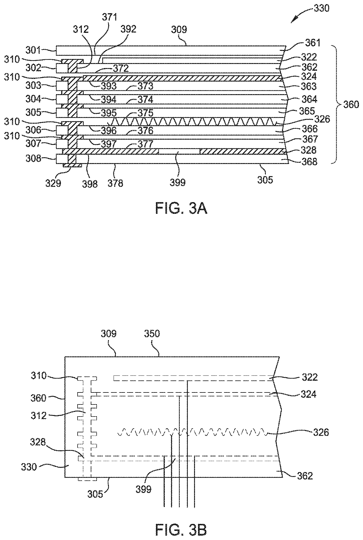
[0035]Additional ground electrical pads 310 are disposed between the second bottom surface 372 and the third top surface 393 proximate the second side surface 362. Vias 312 in the third layer 303 are disposed below the plurality of ground electrical pads 310 on the third top surface 393 proximate the third side surface 363. The ground electrical pads 310, between the second bottom surface 372 and the third top surface 393, are electrically coupled to the vias 312 in the second layer 302 and the vias in the third layer 303. An RF mesh 324 may additionally be disposed between the second bottom surface 372 and the third top surface 393. In one embodiment, the vias 312 in the second layer 302 are aligned with the vias 312 in the third layer. However, the alignment of the vias 312 in the respective second layer 302 and third layer 303 are less important than the electrical conductivity therebetween. In a second embodiment, the vias 312 in the second layer 302 are not aligned with the via...

third embodiment

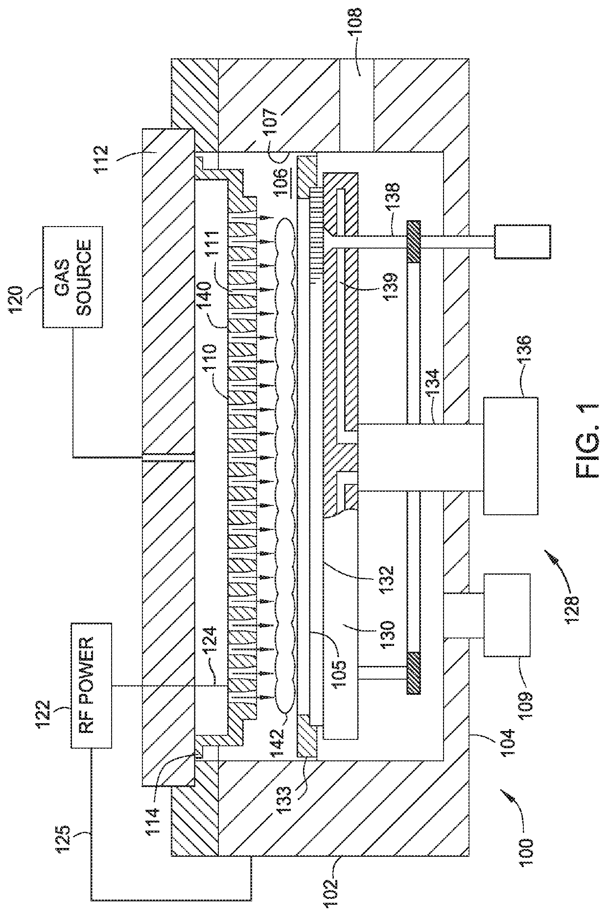
[0047]FIG. 6 is a partial schematic cross-sectional view of a processing chamber 600 including the substrate support assembly 128 according to The processing chamber 600 has a body 601. The body has sidewalls 602, a bottom 604 and a showerhead 612. The sidewalls 602, bottom 604 and showerhead 612 define an interior volume 606. The substrate support assembly 128 is disposed within the interior volume 606. A RF generator 680 is coupled an electrode 682 in the showerhead 612. The RF generator 680 has a RF return path 688 for completing the RF circuit when plasma is present.

[0048]The substrate support assembly 128 has a heater 626, a HV chucking mesh 622, and a RF mesh 624 disposed therein. The substrate support assembly 128 has an exterior surface 629. A metal coating 684 is disposed on the exterior surface 629 of the substrate support assembly 128. The metal coating 684 is formed from nickel, copper, aluminum, molybdenum or other suitable material. The metal coating 684 is part of th...


PUM


Abstract

Disclosed herein is a substrate support assembly having a ground electrode mesh disposed therein along a side surface of the substrate support assembly. The substrate support assembly has a body. The body has an outer top surface, an outer side surface and an outer bottom surface enclosing an interior of the body. The body has a ground electrode mesh disposed in the interior of the body and adjacent the outer side surface, wherein the ground electrode does not extend through to the outer top surface or the outer side surface.

Description

CROSS-REFERENCE TO RELATED APPLICATIONS[0001]This application claims benefit of U.S. Provisional Application Ser. No. 62 / 778,808, filed Dec. 12, 2018 (Attorney Docket No. APPM / 44014800US02), and U.S. Provisional Application Ser. No. 62 / 776,896, filed Dec. 7, 2018 (Attorney Docket No. APPM / 44014800US01) both of which are incorporated by reference in their entirety.BACKGROUNDField[0002]Embodiments of the present disclosure generally relate to plasma processing chambers. More particularly, embodiments of the present disclosure relate to a ground electrode for a substrate support assembly disposed in a plasma processing chamber.Description of the Related Art[0003]Plasma processing systems are used to form devices on a substrate, such as a semiconductor wafer or a transparent substrate. Often the substrate is held to a support for processing. The substrate may be held to the support by vacuum, gravity, electrostatic forces, or by other suitable techniques. During processing, The precurso...

Claims


Application Information

Patent Timeline
Patent Type & Authority Applications(United States)
IPC IPC(8): H01L21/683H01L21/67H01J37/32
CPCH01J37/32724H01L21/67103H01L21/6833H01J2237/002H01J2237/3321H01J37/3244H01J37/32082H01L21/68785H01L21/68757H01L21/68742H01L21/6831H01L21/67109
Inventor RICE, MICHAEL R.PARKHE, VIJAY D.
Owner APPLIED MATERIALS INC
Why Eureka
Try Eureka