Electrical power adapter

a technology of power adapters and adapters, which is applied in the direction of coupling device connections, process and machine control, instruments, etc., can solve the problems of affecting the operation of the adapter

Active Publication Date: 2020-06-18
CHIEN MIN HUNG
View PDF0 Cites 2 Cited by
  • Summary
  • Abstract
  • Description
  • Claims
  • Application Information

AI Technical Summary

Benefits of technology

[0008]In one aspect of the present invention, a travel power adapter system, includes the following: a base unit comprising: an intrinsic prong configuration; a base recess recessed in a top surface of the base unit; a locking slot provided in the base recess; and the intrinsic prong configuration pivotal between an outlet position and a nested position within the base recess; one or more adapter assemblies, each adapter assembly comprising: an extrinsic prong configuration; a coupling sleeve providing apertures for slidably receiving the intrinsic prong configuration; the coupling sleeve dimensioned to slidably nest in the base recess while receiving the intrinsic prong configuration, in an operative associated condition, electrically coupling said extrinsic prong configuration to the intrinsic prong configuration; and a locking unit disposed along an upper surface of the coupling sleeve, that locking unit movable between an unlocked engagement and a locked engagement with the locking slot.

Problems solved by technology

This is not very convenient.
However, there is still a need for improvement in such designs, because the removal of the base unit from the electrical receptacle or socket (especially if not in a straight line, which may demand a user to stoop down or move themselves into another uncomfortable position) may easily generate a vertical (reverse first direction) component force that the adapter assembly to slide from integral prong configuration, risking disconnection and possibly damage to the integral prong configuration and / or the adapter assembly.

Method used


Image

  • Electrical power adapter
  • Electrical power adapter
  • Electrical power adapter

Examples


Embodiment Construction

[0018]The following detailed description is of the best currently contemplated modes of carrying out exemplary embodiments of the invention. The description is not to be taken in a limiting sense, but is made merely for the purpose of illustrating the general principles of the invention, since the scope of the invention is best defined by the appended claims.

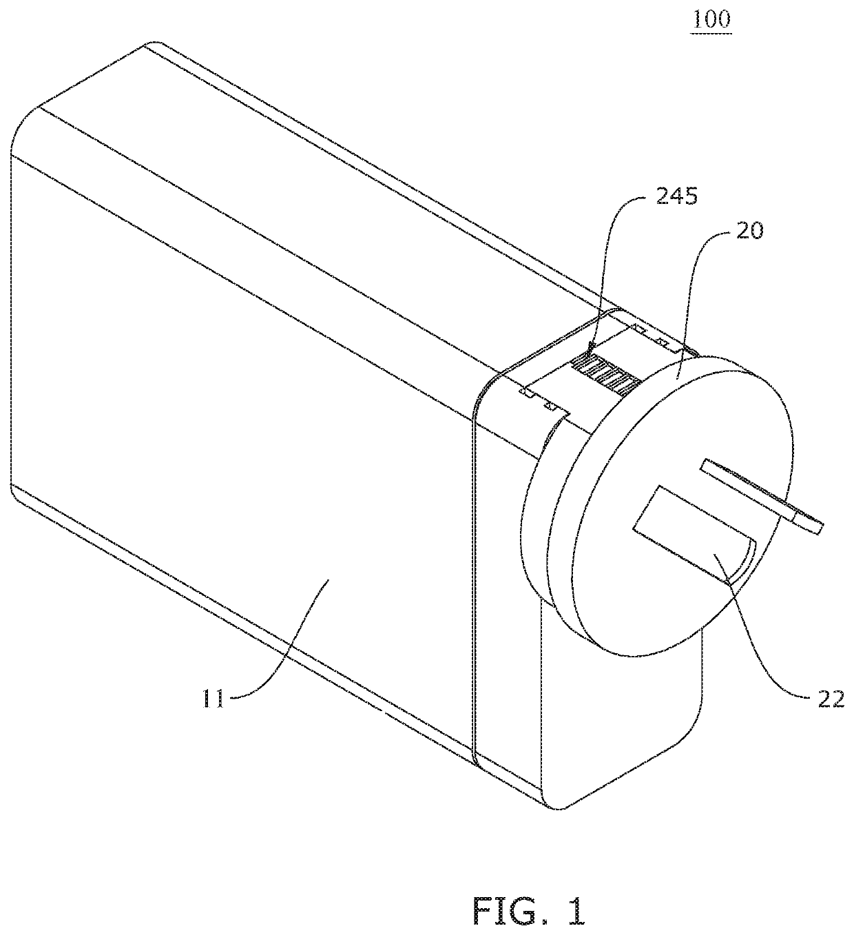
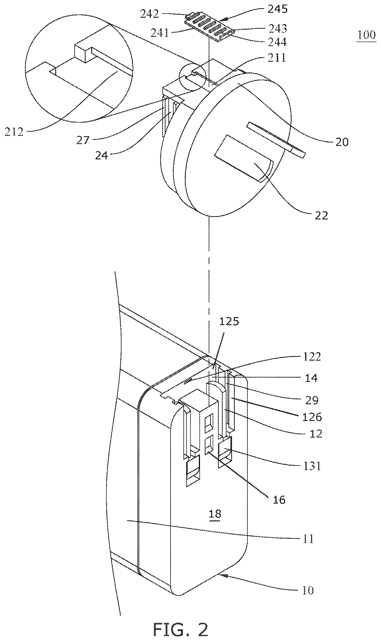
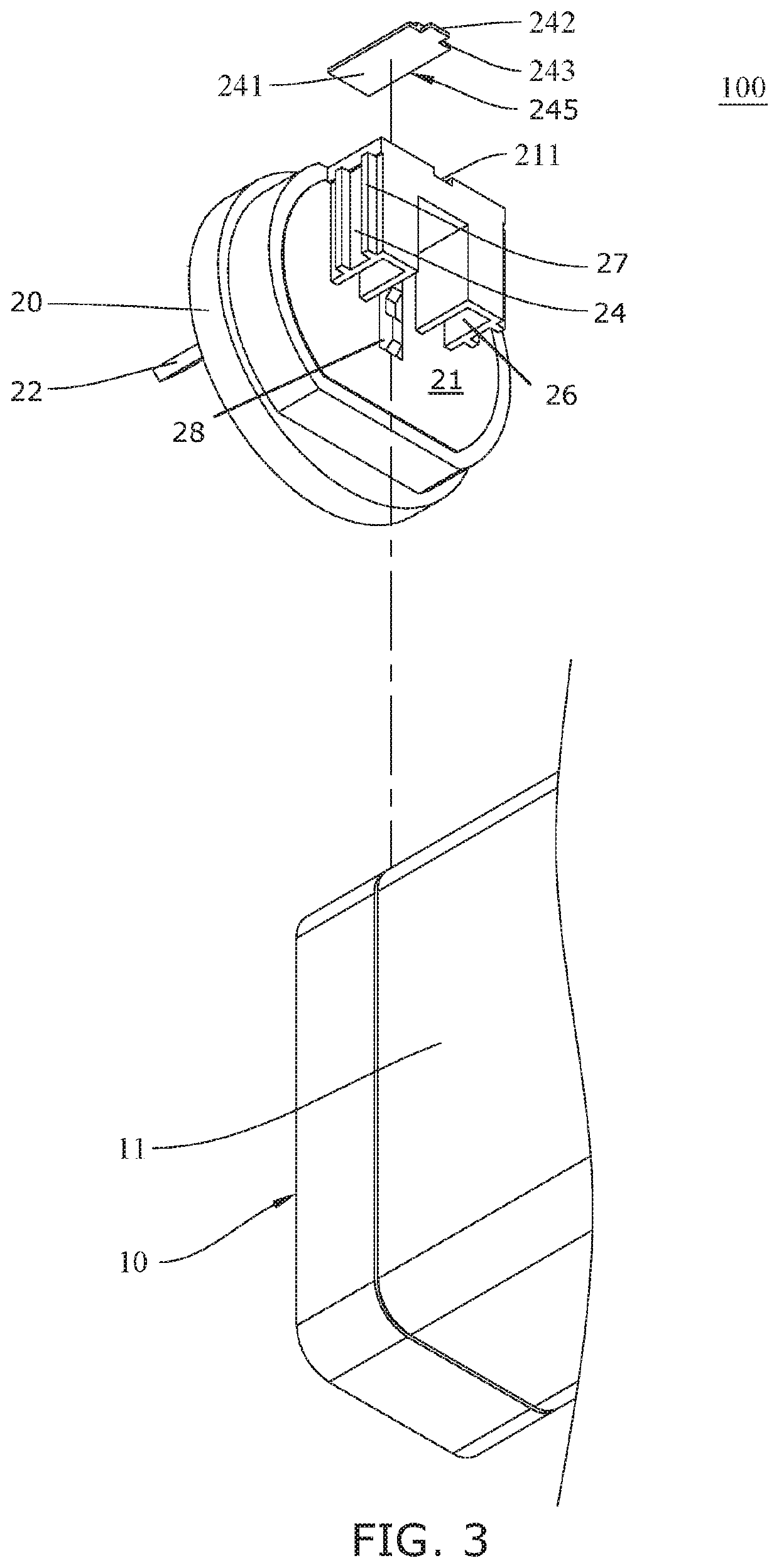
[0019]Broadly, an embodiment of the present invention provides a travel power adapter system. The travel power adapter system includes a base unit and a plurality of adapter assemblies. The base unit provides an integral prong configuration associated with an intrinsic electrical plug standard. Each adapter assembly provides a prong configuration associated with a different extrinsic electrical plug standard. The base unit provides a base recess that the integral prong configuration can pivot into in a nested condition. Each adapter assembly provides coupling sleeves dimensioned to slidably receive, in a first direction, the plu...


PUM


Abstract

A travel power adapter system includes a base unit and a plurality of adapter assemblies. The base unit provides an integral prong configuration associated with an intrinsic electrical plug standard. Each adapter assembly provides a prong configuration associated with a different extrinsic electrical plug standard. The base unit provides a base recess that the integral prong configuration can pivot into in a nested condition. Each adapter assembly provides coupling sleeves dimensioned to slidably receive, in a first direction, the plurality of prongs in the nesting condition, forming an operative association between the base unit and the prong configuration of the adapter assembly, enabling an electrical connection to a receptacle or socket associated with the extrinsic electrical plug standard. The adapter assembly provides a locking unit that engages a locking slot of the base recess, thereby preventing the adapter assembly unintentionally moving in the reverse first direction.

Description

CROSS-REFERENCE TO RELATED APPLICATION[0001]This continuation-in-part non-provisional application claims the benefit of priority of U.S. non-provisional application Ser. No. 16 / 145,686, filed 28 Sep. 2018, the contents of which are herein incorporated by reference.BACKGROUND OF THE INVENTION[0002]The present invention relates to electrical power adapters and, more particularly, to a travel power adapter system embodying an adapter base unit provide in an integral prong configuration associated with an intrinsic electrical plug standard with a track and slide configuration for operatively associating the integral prong configuration interchangeably with one of a plurality of adapter assemblies. Each adapter assembly enables interconnection of the integral prong configuration to an electrical receptacle or socket of an extrinsic electrical plug standard different than that of the intrinsic electrical plug standard. Furthermore, there is a locking engagement that can be formed between ...

Claims


Application Information

Patent Timeline
Patent Type & Authority Applications(United States)
IPC IPC(8): G05F1/45H01R31/06H01R13/66
CPCH01R13/6675G05F1/45H01R31/065H01R2103/00
Inventor CHIEN, MIN-HUNG
Owner CHIEN MIN HUNG
Why Eureka
Try Eureka