

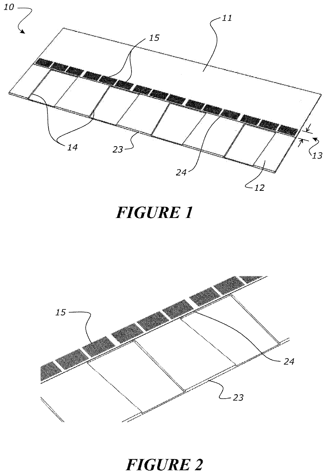
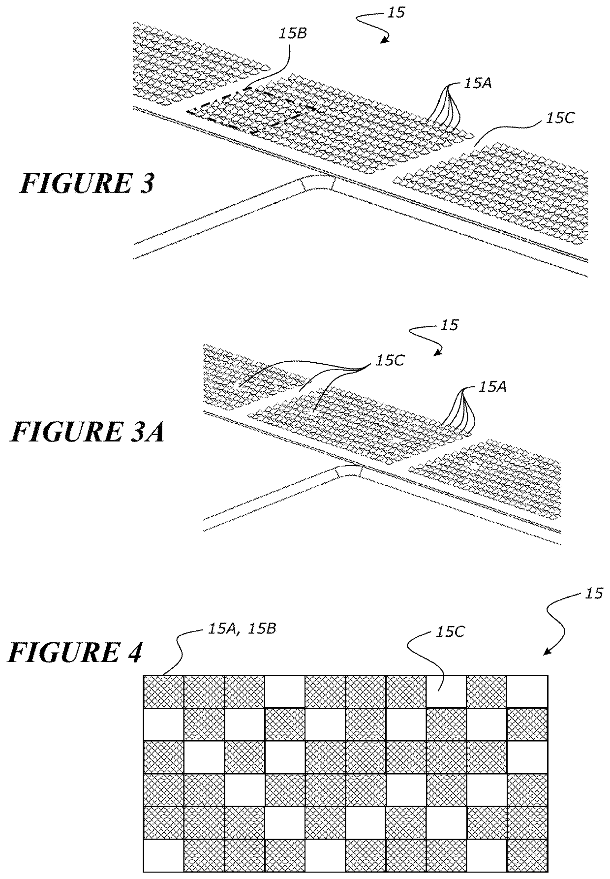
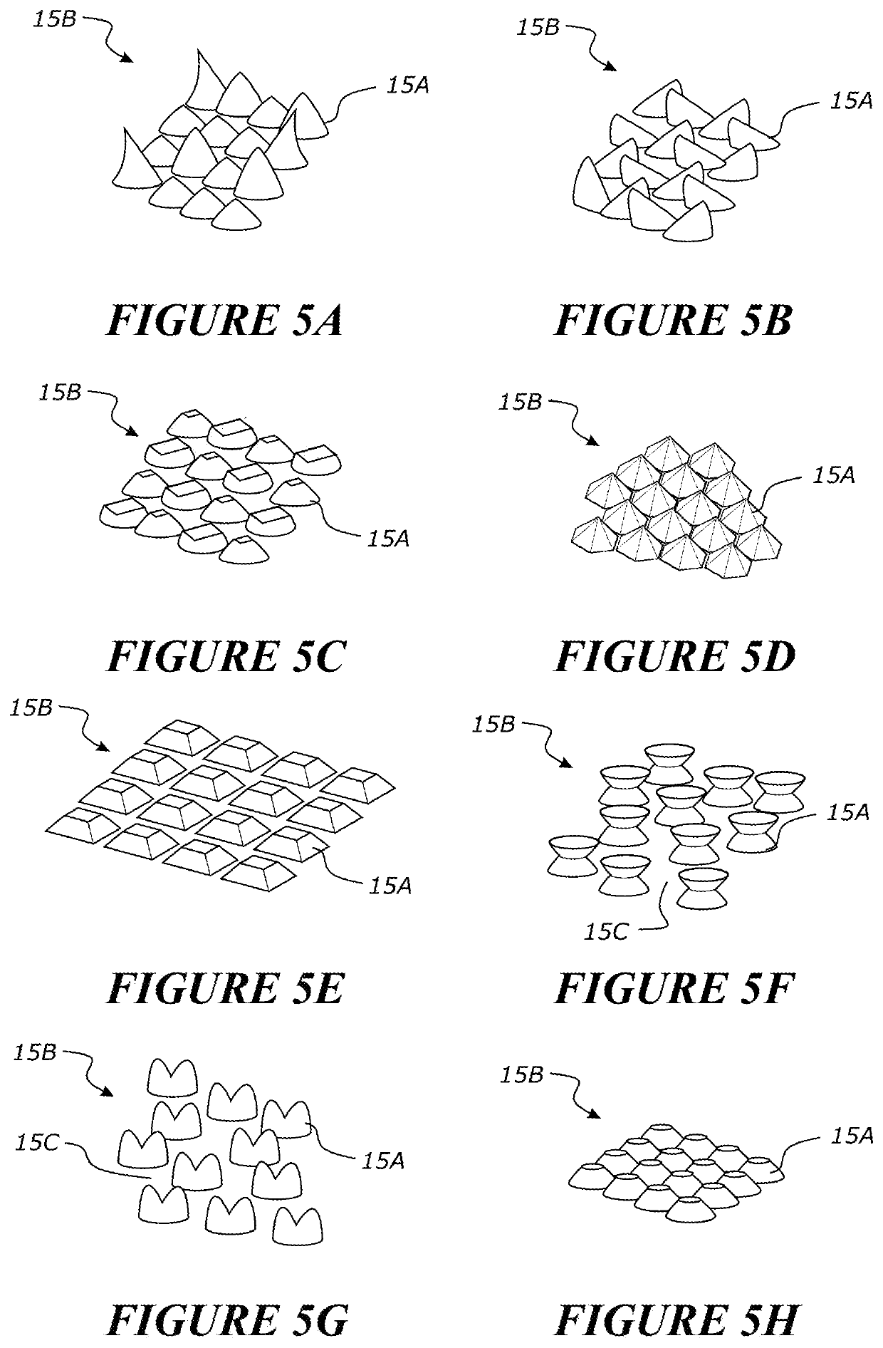
Roofing, cladding or siding module, its manufacture and use
a technology for cladding or siding modules, which is applied in the direction of solar heat collectors for particular environments, photovoltaics, sustainable buildings, etc. it can solve the problems of difficult mass production economics, poor durability and environmental resistance, and insufficient joining/sealing of the adhesive layer on the abutting face of the adjacent modules, etc., to achieve high tac or initial bond strength, different viscosities, or strength or bonding characteristics
- Summary
- Abstract
- Description
- Claims
- Application Information
AI Technical Summary
Benefits of technology
Problems solved by technology
Method used
Image

Examples
Embodiment Construction
[0086]It is to be appreciated that certain aspects, modes, embodiments, variations and features of the invention are described below in various levels of detail in order to provide a substantial understanding of the present technology.
[0087]The present technology is described herein using several definitions, as set forth throughout the specification. Unless otherwise stated, the singular forms “a,”“an,” and “the” include the plural reference. For example, a reference to “a device” includes a plurality of devices.
[0088]As used herein the term “and / or” means “and” or “or”, or both.
[0089]As used herein “(s)” following a noun means the plural and / or singular forms of the noun.
[0090]Relative terms, such as “lower” or “bottom”, “upper” or “top,” and “front” or “back” may be used herein to describe one element's relationship to another element as illustrated in the Figures. It will be understood that relative terms are intended to encompass different orientations of the device in addition...
PUM
 Abstract
Description
Claims
Application Information