Electronic smoking device with capillary buffer

Active Publication Date: 2020-07-02
FONTEM HLDG 1
View PDF3 Cites 3 Cited by
  • Summary
  • Abstract
  • Description
  • Claims
  • Application Information

AI Technical Summary

Benefits of technology

[0005]An electronic vaporizing device is design to avoid leaking of e-liquid by using a capillary buffer between a liquid supply and an atomizer in the housing of the device. The capillary buffer has a liquid conduit extending from the li

Problems solved by technology

If the container is vented, rather than pressure-tight, some e-liquid may be p

Method used


Image

  • Electronic smoking device with capillary buffer
  • Electronic smoking device with capillary buffer
  • Electronic smoking device with capillary buffer

Examples


Embodiment Construction

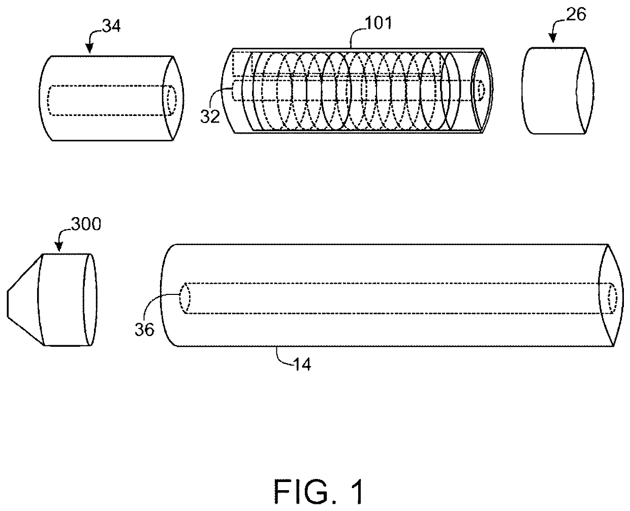
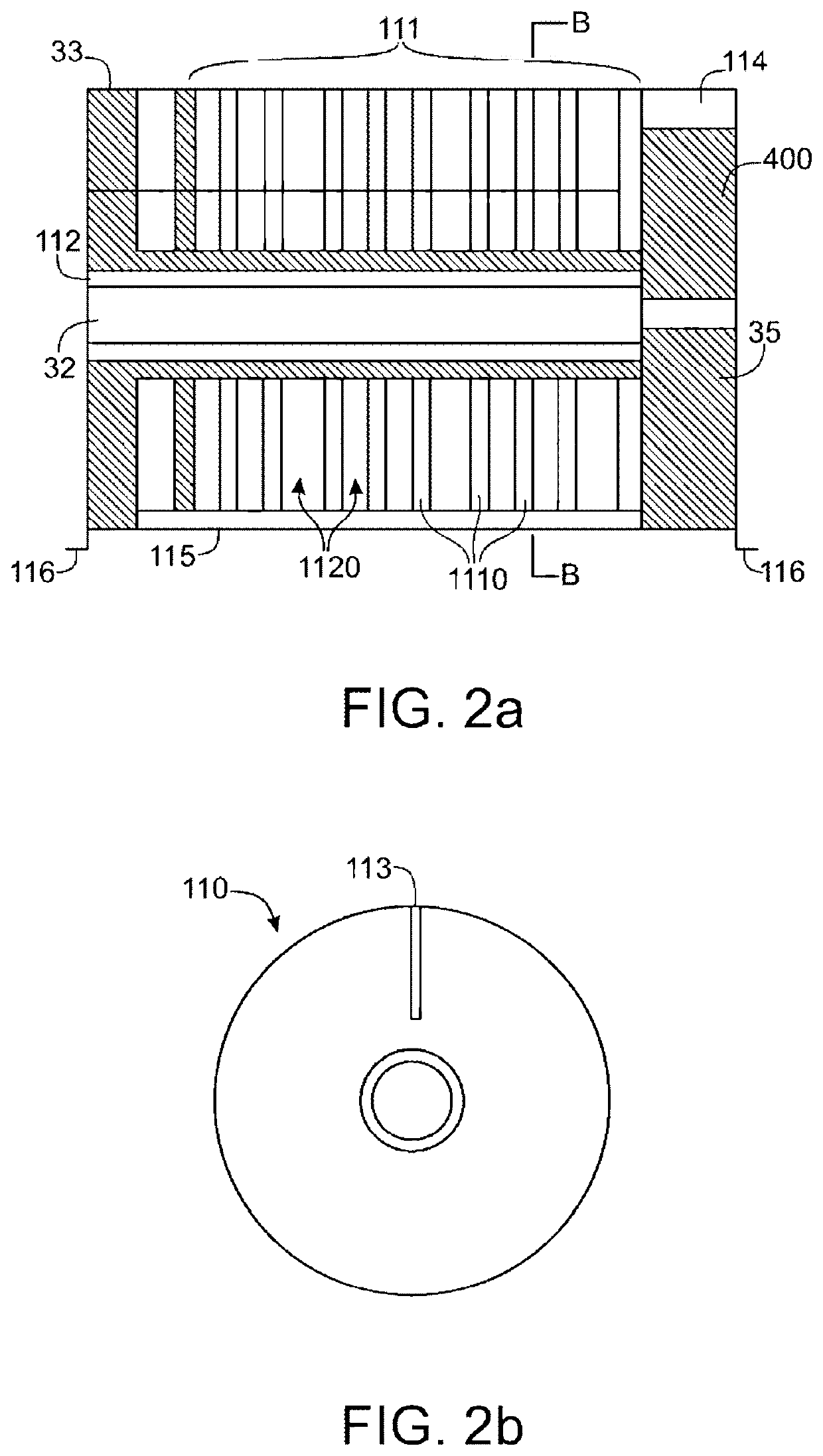
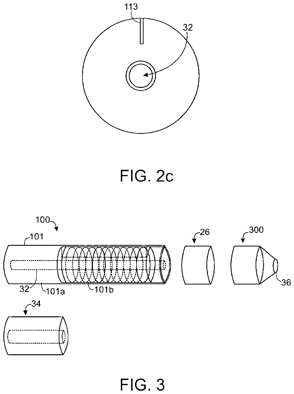
[0016]As is shown in FIG. 6, an electronic vaporizing device 10 typically has a housing comprising a cylindrical hollow tube having an end cap 16. The cylindrical hollow tube may be single piece or a multiple piece tube. In FIG. 6, the cylindrical hollow tube is shown as a two piece structure having a battery portion 12 and an atomizer / liquid reservoir portion 14. Together the battery portion 12 and the atomizer / liquid reservoir portion 14 form a cylindrical tube which is approximately the same size and shape as a conventional cigarette, typically about 100 mm with a 7.5 mm diameter, although lengths may range from 70 to 150 or 180 mm, and diameters from 5 to 20 mm. Vaporizing devices having refillable tanks may have larger diameters, e.g., up to about 30 or 40 mm in diameter.

[0017]The battery portion 12 and atomizer / liquid reservoir portion 14 are typically made of metal or hardwearing plastic and to provide a housing to contain the components of the e-cigarette 10. The battery por...


PUM


Abstract

An electronic smoking device, comprising a capillary buffer having a first end, a second end, a capillary buffer portion between the first end and a second end, and an vapor channel and a liquid conduit formed between first end and the second end and through the capillary buffer portion; the capillary buffer portion is operable to receive under capillary effect excessive liquid from the liquid supply.

Description

TECHNICAL FIELD[0001]The field of the invention is electronic smoking devices, and more particularly electronic smoking devices having improvements to prevent leaking of stored liquid.BACKGROUND[0002]An electronic smoking device, such as an electronic cigarette (e-cig or e-cigarette), electronic cigar, personal vaporizer (PV) or electronic nicotine delivery system (ENDS) is a battery-powered vaporizer which simulates smoking tobacco. These devices produce a vapor by supplying a liquid to an atomizer. E-liquid refers to the liquid which is atomized to produce the vapor. The main ingredients of e-liquid are usually a mix of propylene glycol (PG), glycerin (G), and / or polyethylene glycol 400 (PEG400). Various concentrations of alcohol mixed with flavorings, and nicotine, are also often included.[0003]E-liquid is often sold in bottles or pre-filled disposable cartridges. Some e-liquid cartridges are prefilled by the manufacturer. In some cases, e-liquid is filled directly into a cartrid...

Claims


Application Information

Patent Timeline
IPC IPC(8): A24F40/44A24F40/48A24F40/10A24F40/485
CPCA24F40/48A24F40/44A24F40/10A24F40/485
Inventor TONG, XINLIANG
Owner FONTEM HLDG 1
Why Eureka
Try Eureka