Platelet oscillation storage box

a technology of platelet and storage box, which is applied in the field of medical technology, can solve the problems of wasting platelets, clots of storage liquid, and low visibility, and achieve the effect of reducing energy loss and extending the storage time of platelets

Inactive Publication Date: 2020-07-02
QIAN GUOCHENG
View PDF0 Cites 27 Cited by
  • Summary
  • Abstract
  • Description
  • Claims
  • Application Information

AI Technical Summary

Benefits of technology

[0015]The beneficial effect of the present invention is that the test tube in which the platelets are stored can be clamped in the storage cavity by the clamping device of the present invention, and the storage cavity is independent and communicates with the thermostat independently. The constant temperature conditions in the storage chamber are blocked, reducing the loss of energy, without destroying the constant temperature environment in other storage chambers, and extending the storage time of platelets. Secondly, the sealing device can keep the storage chamber in a sealed state, and during the oscillation process The sealing cover and the storage chamber are always locked to ensure constant temperature in the storage chamber.

Problems solved by technology

When the door of the box is opened, the internal temperature of the box is out of control, and the oscillation stops, causing the storage conditions of other stored platelets to fail to meet the standards, which leads to the clot of the storage liquid, which is unusable and wastes platelets.
Second, the existing platelet storage box The test tubes are placed uniformly and the visibility is low.

Method used


Image

  • Platelet oscillation storage box
  • Platelet oscillation storage box
  • Platelet oscillation storage box

Examples


Embodiment Construction

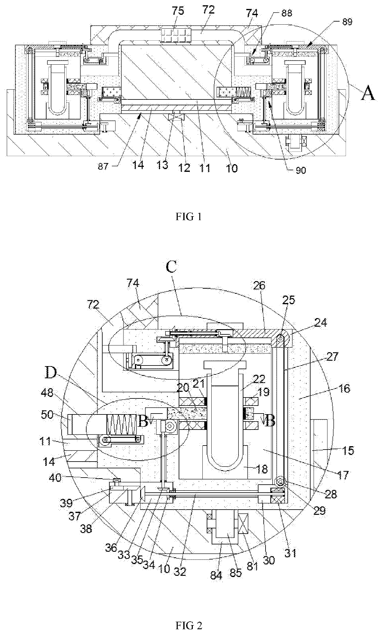
[0023]The present invention is described in detail below with reference to FIGS. 1-5. For convenience of description, the orientation described below is defined as follows: the up-down, left-right, front-back direction described below is consistent with the up-down, left-right, front-back direction of the projection relationship of FIG. 1 itself.

[0024]The present invention relates to a platelet oscillation storage box, which is mainly used for storing platelets. The present invention will be further described below with reference to the accompanying drawings of the present invention:

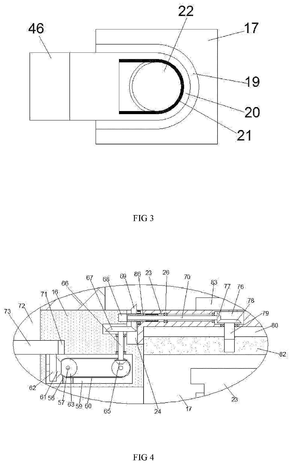
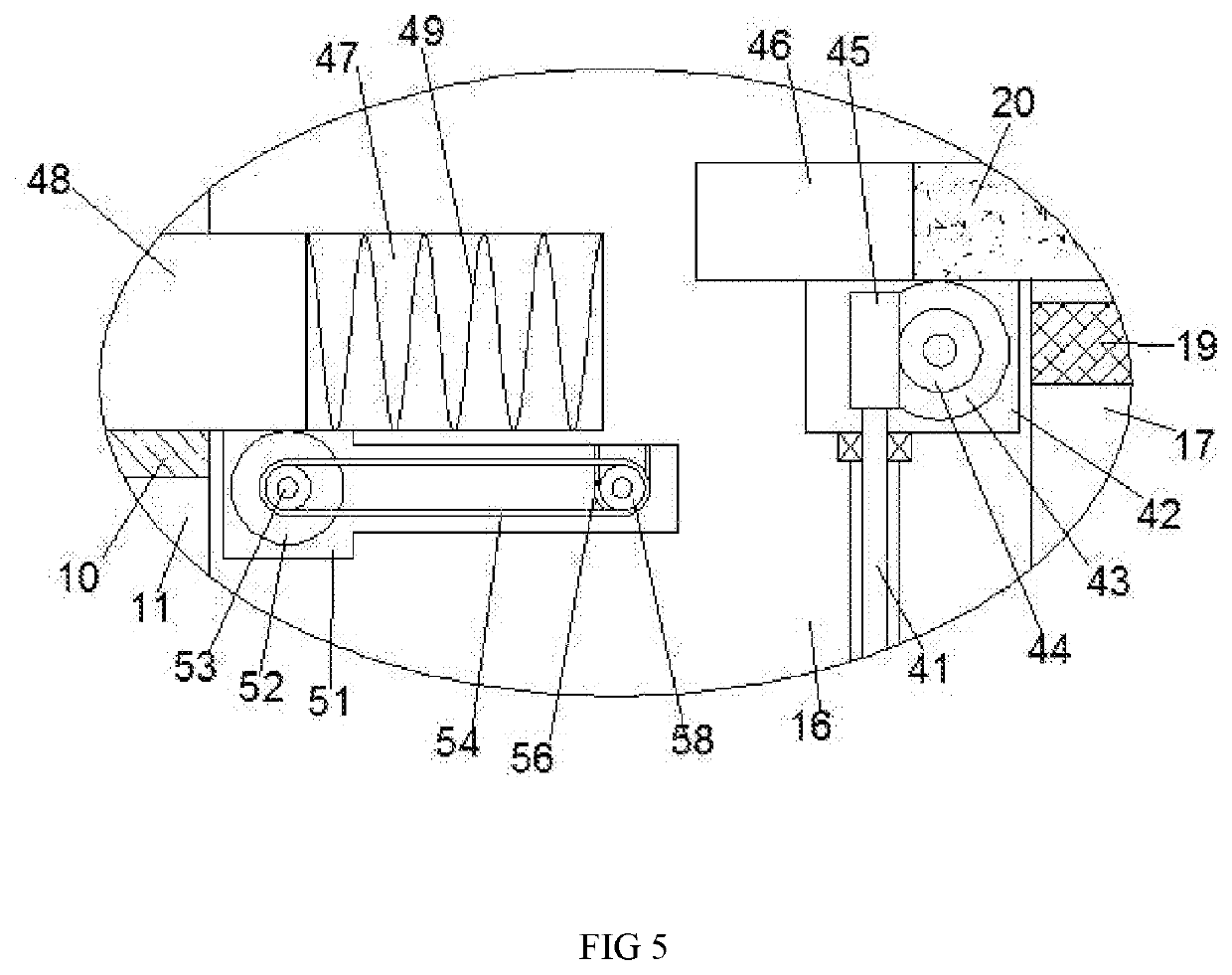
[0025]A platelet oscillation storage box according to the present invention includes a box body 10, which is provided with six circular arrays and connected rotating cavities 15, and five storage blocks 16 in the rotating cavities. A storage cavity 17 is provided in the storage block 16, and a placement block 18 is fixed on the lower end wall of the storage cavity 17. An end of the storage cavity 17 near...


PUM


Abstract

The invention discloses a platelet oscillating storage box, which includes a box body. The box body is provided with six circular array and connected rotating cavities. There are five storage blocks in the rotating cavity, and the storage blocks are provided with storage. A cavity, a storage block is fixed on the lower end wall of the storage cavity, and an end of the storage cavity close to the center of the array is provided with a fixed block that is symmetrical up and down, and a movable clamping block is provided between the fixed blocks. The clamping device can be used to clamp the test tube containing the platelets in the storage cavity, and the storage cavity is independent and communicates with the thermostat independently. When taking or storing platelets, the thermostatic conditions in the storage cavity to be placed are blocked. Cut off, reducing energy loss, without destroying the constant temperature environment in other storage chambers, and prolonging the storage time of platelets. Secondly, the sealing device can keep the storage chamber sealed, and the sealing cover and the storage chamber remain locked during the oscillation process. Ensure constant temperature in the storage chamber.

Description

CROSS-REFERENCES TO RELATED APPLICATIONS[0001]The present application claims priority from Chinese application No. 2019111761672 filed on Sep. 19, 2019 which is hereby incorporated by reference in its entirety.TECHNICAL FIELD[0002]The invention relates to the field of medical technology, in particular to a platelet oscillation storage box.BACKGROUND OF THE INVENTION[0003]The storage conditions of platelets are continuous shaking at a constant temperature and a short storage time. The existing platelet storage box is provided with a single opening and closing box door, and the platelet test tubes are placed in the internal storage cavity of the box uniformly. When the door of the box is opened, the internal temperature of the box is out of control, and the oscillation stops, causing the storage conditions of other stored platelets to fail to meet the standards, which leads to the clot of the storage liquid, which is unusable and wastes platelets. Second, the existing platelet storage...

Claims


Application Information

Patent Timeline
Patent Type & Authority Applications(United States)
IPC IPC(8): A61J1/05B65D25/02B01F11/00
CPCA61J1/05B01F11/0005B65D25/02B01F31/20B01F31/201
Inventor QIAN, GUOCHENG
Owner QIAN GUOCHENG
Why Eureka
Try Eureka