
Failure detection device for an external sensor and a failure detection method for an external sensor

a failure detection and sensor technology, applied in the field of failure detection devices for external sensors and failure detection methods for external sensors, can solve the problems of limiting the automatic driving of a subset of functions, and the limited effect of achieving automatic driving without driver intervention, and achieve the effect of prolonging the cruisable distance of automatic driving

Active Publication Date: 2020-07-02
HITACHI LTD
View PDF0 Cites 7 Cited by
  • Summary
  • Abstract
  • Description
  • Claims
  • Application Information

AI Technical Summary

Benefits of technology

The technical effect of this patent is to improve the ability of automatic driving systems to cruise for longer distances without needing a driver to intervene.

Problems solved by technology

For this reason, in a case where the recognition accuracy of a certain sensor is thought to be reduced, the influence of the sensor is removed even if the sensor is actually successful in correctly recognizing a target object, thereby necessitating driver intervention and limiting the automation of driving to a subset of functions.
Consequently, the effect of achieving automatic driving without driver intervention is limited to only the cases in which the environment is not unfavorable for any of the sensors.

Method used


Image

  • Failure detection device for an external sensor and a failure detection method for an external sensor
  • Failure detection device for an external sensor and a failure detection method for an external sensor
  • Failure detection device for an external sensor and a failure detection method for an external sensor

Examples


first embodiment

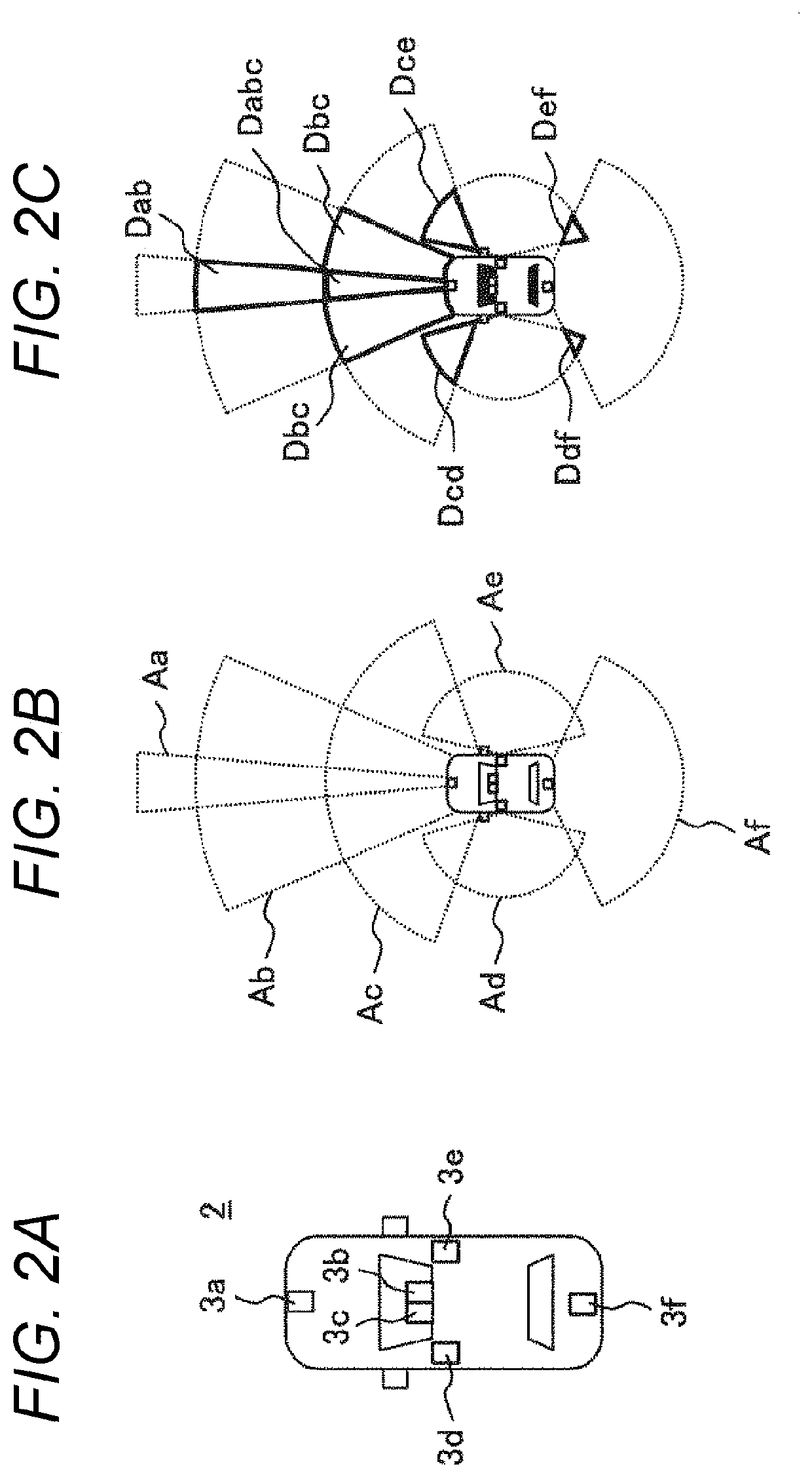
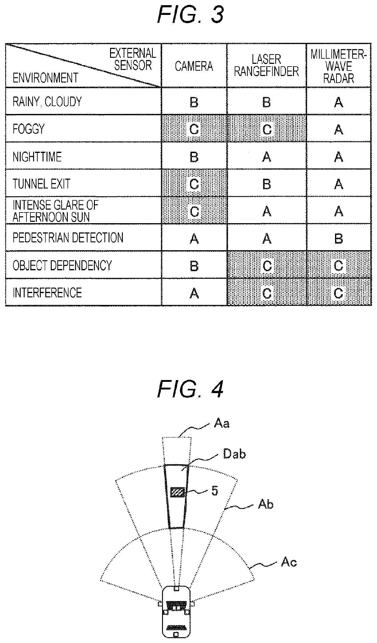
[0023]A failure detection device 1 according to a first embodiment of the present invention will be described according to FIGS. 1 to 7.

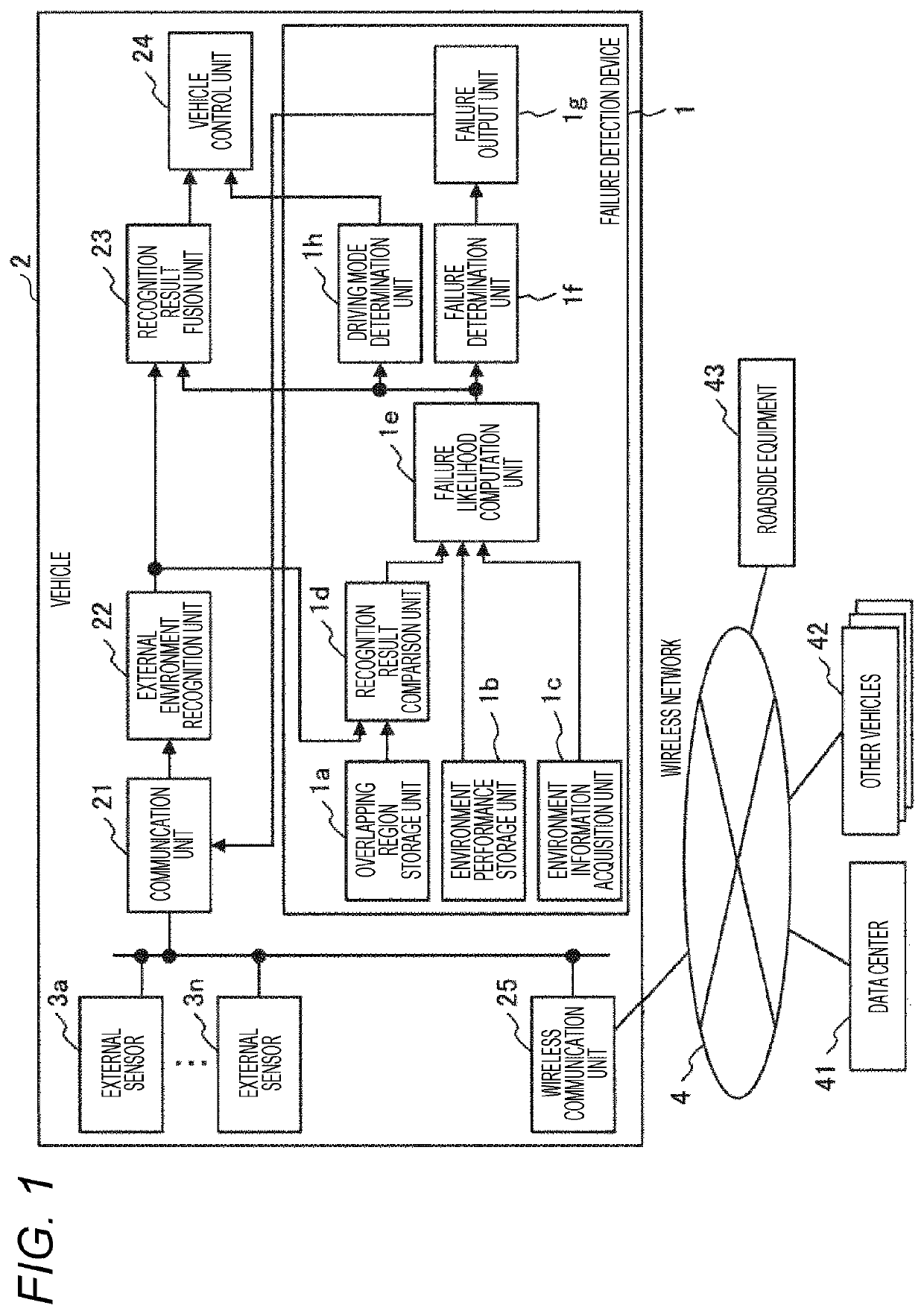
[0024]FIG. 1 is a function block diagram illustrating a configuration of a vehicle 2 provided with the failure detection device 1 according to the present embodiment.

[0025]As illustrated herein, in addition to the failure detection device 1, the vehicle 2 includes a communication unit 21, an external environment recognition unit 22, a recognition result fusion unit 23, a vehicle control unit 24, a wireless communication unit 25, and a plurality of external sensors 3 (3a to 3n) that detect the surrounding environment of the vehicle 2. Among these, the external sensors 3, the communication unit 21, and the wireless communication unit 25 are interconnected via a dedicated line inside the vehicle 2. Also, the wireless communication unit 25 is connected to a data center 41, other vehicles 42, roadside equipment 43, and the like through a wireless network...

second embodiment

[0058]Next, a failure detection device 1 according to a second embodiment of the present invention will be described according to FIGS. 8 and 9. Note that duplicate description will be omitted for points shared in common with the first embodiment.

[0059]When computing the failure likelihood, the failure likelihood computation unit 1e of the present embodiment not only considers the environment-dependent performance of the external sensors like in the first embodiment, but also considers an abnormality record that stores an abnormality occurrence history of the other vehicles 42 in association with environment information (such as position and weather) at the time of each abnormality.

[0060]FIG. 8 is a diagram illustrating a configuration of the failure detection device 1 according to the second embodiment. The differences from FIG. 1 are that an accumulated information acquisition unit 1i is added to the failure detection device 1, the output of which is input into the failure likelih...


PUM


Abstract

A failure detection device that detects a failure in a plurality of external sensors onboard a vehicle, the failure detection device comprises: an overlapping region storage unit that stores an overlapping region of detection areas of the external sensors; an environment performance storage unit that stores an environment-dependent performance of sensing of the external sensors; an environment information acquisition unit that acquires environment information about the vehicle; a recognition result comparison unit that compares recognition results of an object in the overlapping region from the external sensors; a failure likelihood computation unit that computes a failure likelihood of each external sensor based on a comparison result of the recognition results, the environment information, and the environment-dependent performance; and a failure determination unit that determines a failure in each external sensor based on the failure likelihood of each of the external sensors.

Description

CLAIM OF PRIORITY[0001]The present application claims priority from Japanese patent application serial no. 2018-242370 filed on Dec. 26, 2018, the contents of which are hereby incorporated by reference into this application.BACKGROUND OF THE INVENTION1. Field of the Invention[0002]The present invention relates to a failure detection device for an external sensor that recognizes the environment surrounding a moving object such as an automobile, and a failure detection method for an external sensor.2. Description of the Related Art[0003]A moving object such as an automobile acquires environment information, such as the road conditions, weather, and the position of the moving object itself, through a plurality of external sensors. Additionally, technology has been developed in which all or part of the control of the travel of a vehicle is automated based on recognition results from these external sensors. In such a vehicle, a fusion of recognition results from each of the external sens...

Claims


Application Information

Patent Timeline
Patent Type & Authority Applications(United States)
IPC IPC(8): B60W50/029
CPCB60W50/029B60W2050/021B60W2050/0215B60W50/023B60W2050/0292B60W50/032B60W60/00186B60W60/00182B60W2556/50B60W2556/55B60W2556/10B60W2555/20B60W50/0205G07C5/0808B60W2556/45B60W2420/408B60W2420/403
Inventor NISHIDA, TAKEHISAOKUDE, MARIKOMUTO, KAZUO
Owner HITACHI LTD
Learn More