System, testing assembly and method for fatigue testing a wind turbine blade
a wind turbine and blade technology, applied in the field of system for fatigue testing can solve the problems of small damage, fatigue crack or other failure of wind turbine blades, and modeling limitations
- Summary
- Abstract
- Description
- Claims
- Application Information
AI Technical Summary
Benefits of technology
Problems solved by technology
Method used
Image
Examples
first embodiment
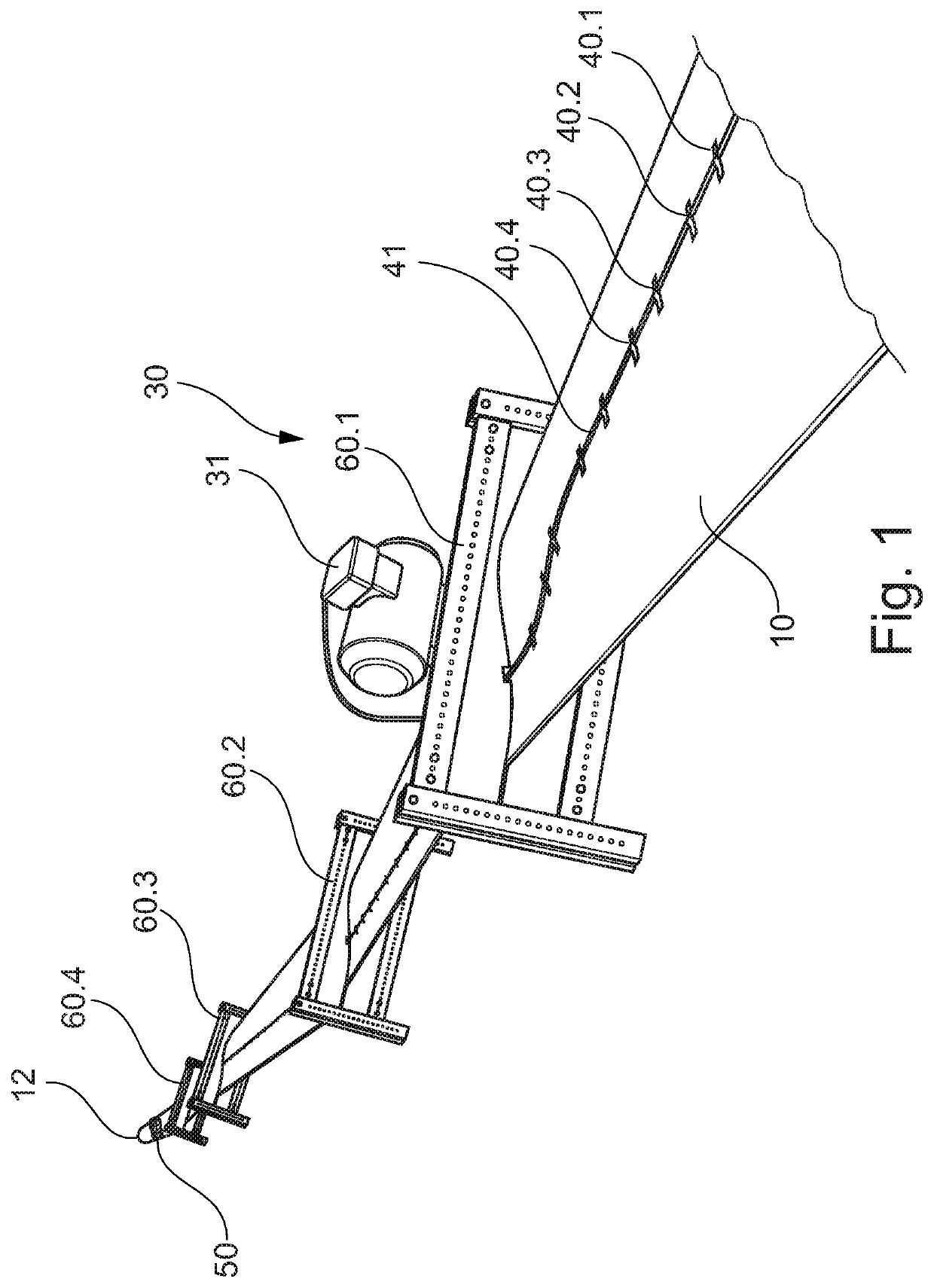
[0030]FIG. 1 shows an embodiment of the testing assembly according to a testing assembly according to embodiments of the invention. The testing assembly comprises a wind turbine blade 10, of which a tip end 12 is shown but part of the wind turbine blade 10 close to a root end 11 as well as a mounting 20, in which the root end 11 is retained, are not shown in this figure. The testing assembly is mounted in the mounting 20 so that it is hanging.
[0031]Four loads 60.1, 60.2, 60.3, and 60.4 are attached to the wind turbine blade 10 spaced apart from each other. The loads 60.1, 60.2, 60.3, and 60.4 are designed as yokes in this embodiment. In particular, each of the yokes comprises four bars attached to one another to form a rectangular shape. Two holding plates are arranged in between the four bars. The holding plates are at one of their sides designed corresponding to the shape of the wind turbine blade 10 at the position of attachment of the yokes to the wind turbine blade 10. The load...
second embodiment
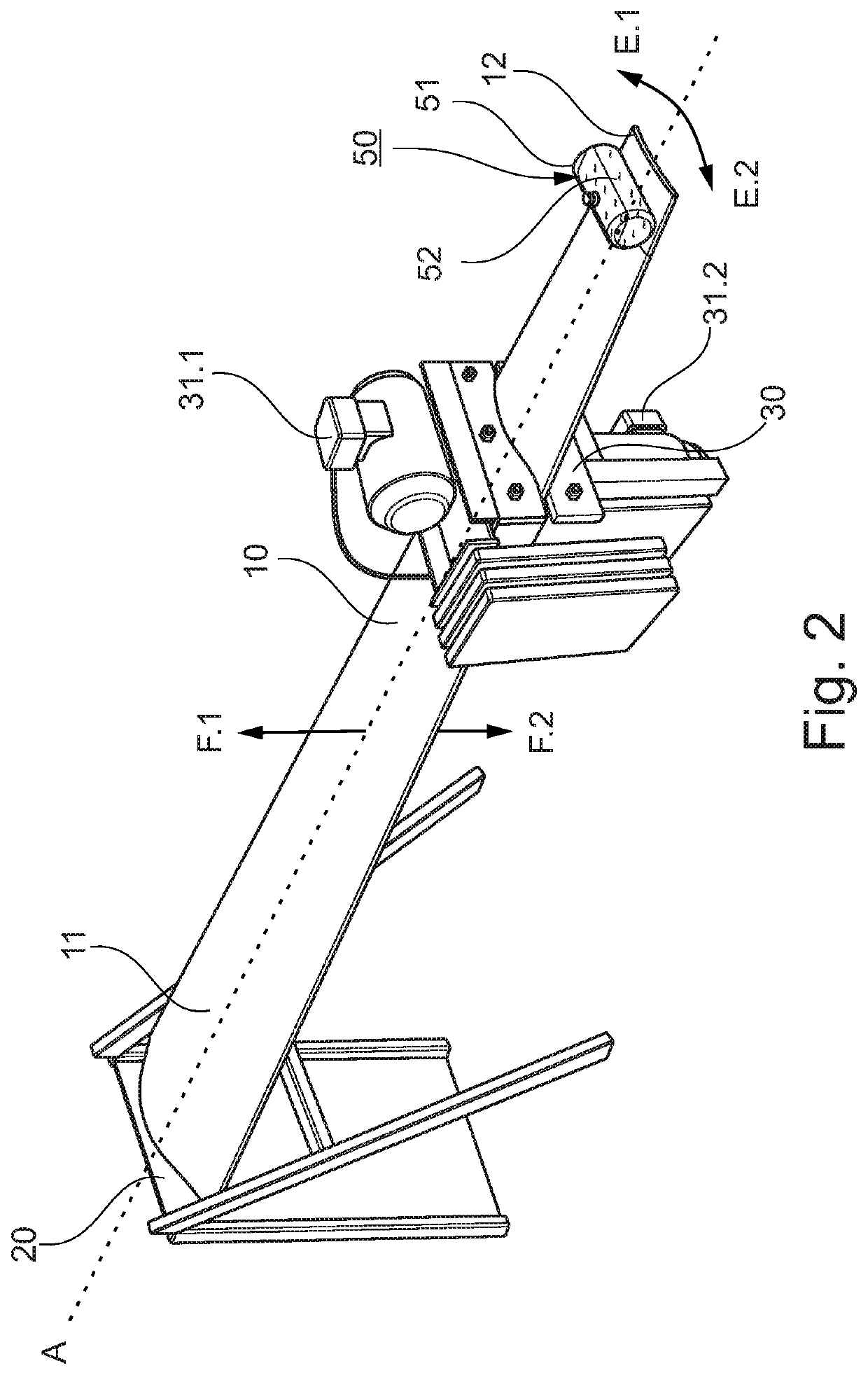
[0035]FIG. 2 shows an embodiment of the testing assembly according to a testing assembly according to embodiments of the invention. This testing assembly with a relatively short wind turbine blade 10 of 5 meters length has been used for evaluating tuning parameters of the tuned liquid damper 50. For illustration purposes only, the measurement devices 40 and wire 41 have been omitted in FIG. 2.
[0036]The root end 11 of the wind turbine blade 10 being retained in the mounting 20 is shown in FIG. 2. Moreover, the longitudinal axis A of the wind turbine blade 10 is shown. Also, flapwise directions F.1 and F.2 and edgewise directions E.1 and E.2 of the wind turbine blade 10 are shown, into which the wind turbine blade 10 is moved, when the actuator assembly 30 with both its actuators 31.1 and 31.2 are being operated. Actuator 31.1 is arranged in the edgewise directions E.1 and E.2 and actuator 31.2 is arranged in the flapwise directions F.1 and F.2. Thereby, when operating the actuator 31...
PUM
 Abstract
Description
Claims
Application Information
 - R&D
- Intellectual Property
- Life Sciences
- Materials
- Tech Scout
- Unparalleled Data Quality
- Higher Quality Content
- 60% Fewer Hallucinations
Browse by: Latest US Patents, China's latest patents, Technical Efficacy Thesaurus, Application Domain, Technology Topic, Popular Technical Reports.
© 2025 PatSnap. All rights reserved.Legal|Privacy policy|Modern Slavery Act Transparency Statement|Sitemap|About US| Contact US: help@patsnap.com


