Patient specific stemless prosthesis anchor components

a stemless, patient-specific technology, applied in the direction of prosthesis, shoulder joints, medical science, etc., can solve the problems of more difficult to secure the stemless humeral component to the humerus, disadvantageous removal of the stem, and difficult removal of the humeral component, so as to reduce bone erosion or degradation, and enhance initial pull-out and back-out resistance

Pending Publication Date: 2020-07-09
HOWMEDICA OSTEONICS CORP
View PDF0 Cites 20 Cited by
  • Summary
  • Abstract
  • Description
  • Claims
  • Application Information

AI Technical Summary

Benefits of technology

[0007]Accordingly, there is a need for additional stemless components or prostheses designed to reduce bone erosion or degradation due to stress shielding and in some cases to preserve bone in initial implantation while enhancing initial pull-out and back-out resistance. The reduction of bone erosion and the enhanced pull-out and back-out resistance can be augmented in patient specific embodiments. Preferably enhanced initial dislodgement resistance will also provide excellent long term fixation.

Problems solved by technology

In certain cases, insertion of the stem disadvantageously requires bone to be removed to fit the stem to the medullary canal due to patient-to-patient anatomical variation.
Another disadvantage of this approach is that integration of the stem into the bone through a natural process of bone ingrowth can make it difficult to remove the humeral component if it becomes necessary to replace the humeral component with another device.
Stemless humeral component designs can be more challenging to secure to the humerus.

Method used


Image

  • Patient specific stemless prosthesis anchor components
  • Patient specific stemless prosthesis anchor components
  • Patient specific stemless prosthesis anchor components

Examples


Embodiment Construction

[0059]While the present description sets forth specific details of various embodiments, it will be appreciated that the description is illustrative only and should not be construed in any way as limiting. Furthermore, various applications of such embodiments and modifications thereto, which may occur to those who are skilled in the art, are also encompassed by the general concepts described herein. Each and every feature described herein, and each and every combination of two or more of such features, is included within the scope of the present invention provided that the features included in such a combination are not mutually inconsistent.

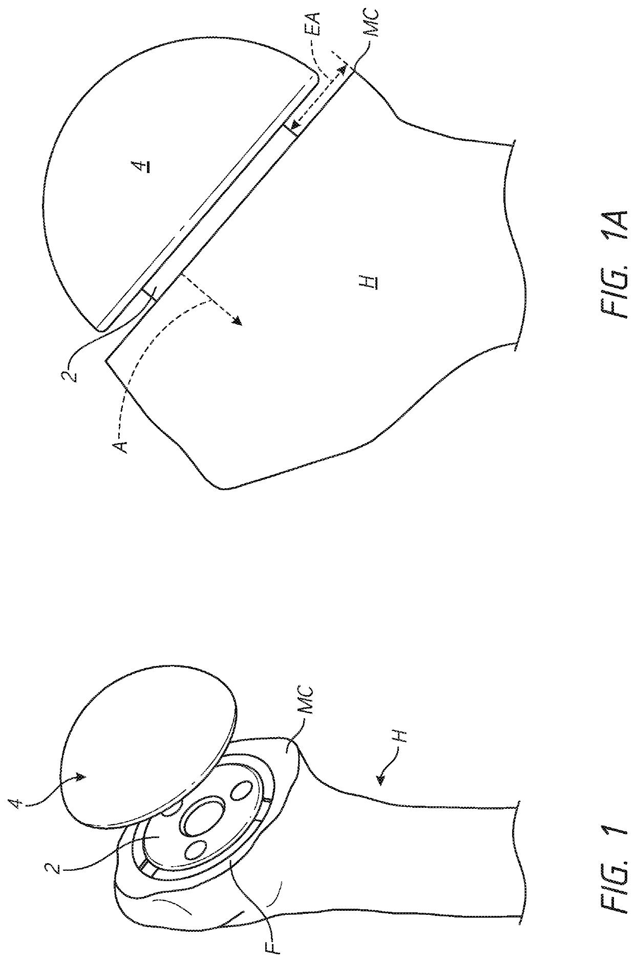
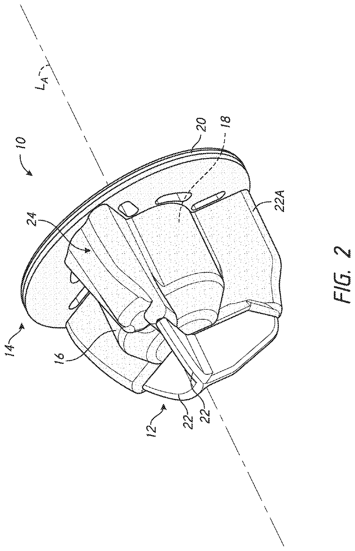
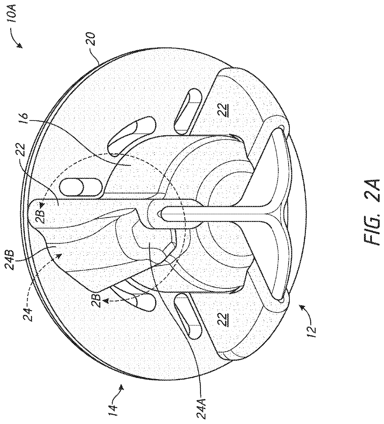
[0060]Section I (FIGS. 1-1A) of this application discusses the problem of stress shielding in the context of a humeral implant. In Section II (FIG. 4), a kit that includes both anatomic and reverse shoulder implant assemblies for treating shoulder conditions that can be, patient specific at least in part, are discussed. Section III (FIGS. 2-3) is...


PUM


Abstract

A stemless humeral anchor (10) includes a first end (12) configured to be embedded in a proximal portion of a humerus and a second end (14); a mating portion (16) for an articular component; a transversely extending collar (20); and a rotation control feature (22, 22A) for resisting rotation when the stemless humeral anchor is implanted. A void filling protrusion (24) can extend circumferentially from rotation control feature and can include a porous shell (26), in which a void filling component (28) can be disposed. The rotation control feature can comprise arms. One or more arms (22A) can have a larger radial extent than the others (22). A prosthesis assembly includes a base member (104) that has a helical structure (224) and one or more pathways (300). The pathway is accessible from a proximal end and is directed distally through the helical structure. The pathway is located inward of an outer periphery of the helical structure. The pathway extends in a space between successive portions of the helical structure. The prosthesis assembly includes a locking device (108) that has a support member (132) and an arm (110) that projects away from the support member. The arm is disposed in the pathway when the support member is disposed adjacent to the proximal end of the base member. The arm is disposed through bone in the space between successive portions of the helical structure when the prosthesis assembly is implanted.

Description

INCORPORATION BY REFERENCE TO ANY PRIORITY APPLICATIONS[0001]Any and all applications for which a foreign or domestic priority claim is identified in the Application Data Sheet as filed with the present application are hereby incorporated by reference under 37 C.F.R. § 1.57.BACKGROUND OF THE INVENTIONField of the Invention[0002]The present disclosure relates to a stemless prosthesis anchor component of a joint prosthesis. Description of the Related Art[0003]Skeletal joints have a variety of configurations providing for a wide range of smooth movement of two or more bones relative to each other. For example, in a shoulder joint, the head of the humerus interacts with the glenoid cavity of the scapula in a manner similar to a “ball and socket” joint. Over time, it may become necessary to replace a joint, such as the shoulder joint, with a prosthetic joint. The prosthetic joint can include components mounted to one, two or more than two bones at the joint. For example, the prosthetic j...

Claims


Application Information

Patent Timeline
Patent Type & Authority Applications(United States)
IPC IPC(8): A61F2/40A61F2/30A61F2/46
CPCA61F2/4637A61F2/4612A61F2002/3093A61F2002/30289A61F2002/30011A61F2/4003A61F2002/30408A61F2/4059A61F2002/4062A61F2002/30574A61F2/30942A61F2/30767A61F2002/30405A61F2002/305A61F2002/4007A61F2002/4074A61F2250/0024
Inventor KNOX, KEVIN P.GARGAC, SHAWN M.SCHEIBEL, MARKUS
Owner HOWMEDICA OSTEONICS CORP
Why Eureka
Try Eureka