Method and apparatus for providing flitches to an edger

a technology of edger and blade, applied in the field of processing wood products, can solve the problems of significant delay, as much as a few seconds, and significant gap between, and achieve the effect of reducing the number of cuts

Active Publication Date: 2020-07-09
SALEM EQUIP
View PDF3 Cites 0 Cited by
  • Summary
  • Abstract
  • Description
  • Claims
  • Application Information

AI Technical Summary

Benefits of technology

[0012]In one embodiment of the apparatus, each flitch is stopped in a transfer ready holding position and then is engaged to be moved by a charger subassembly. Each charger subassembly includes a lower flitch carrier member spaced apart from another along the length of the flitch, and each flitch carrier member includes a turntable portion which can engage the bottom of the flitch. A respective upper contact pad is moved down by an actuator to press the flitch onto the turntable portion of the flitch carrier member. The upper contact pad is positioned located directly above the turntable portion of the flitch carrier member. The flitch carriers are moved to carry the flitch laterally to the edger ready position, in a desired location and orientation above the edger infeed mechanism in a very short time. Each of the upper contact pads is controlled to move together with and remain aligned with the turntable of its corresponding flitch carrier member as the feed forks and contact pads move the flitch to the desired edger ready position with respect to an infeed mechanism of the edger that will result in the maximum commercial value of the boards that can be obtained from that flitch.
[0014]In one embodiment of the apparatus, when a flitch is positioned above the infeed mechanism, a set of tipples adjacent the infeed mechanism is moved upward and into supporting contact with the underside of the flitch. At the same time, an infeed press roller associated with a tipple is lowered into contact with the upper side of the flitch, so the flitch is held in the correct location. Once the flitch has been grasped and is held by the tipples and the press rollers the flitch carrier members and the upper contact pads release the flitch and are retracted. The infeed press rollers keep the flitch in the desired orientation and location established by the carrier members and pressure pads and in contact with and supported by the tipples.

Problems solved by technology

As a result, there is a significant gap between the tail end of a flitch being sawn in the edger and the head end of the next flitch to enter the edger saw blades.
As a result of the gaps between flitches being fed into an edger, there may be a significant delay, or dead time, of as much as a few seconds between flitches going through an edger.

Method used


Image

  • Method and apparatus for providing flitches to an edger
  • Method and apparatus for providing flitches to an edger
  • Method and apparatus for providing flitches to an edger

Examples


Embodiment Construction

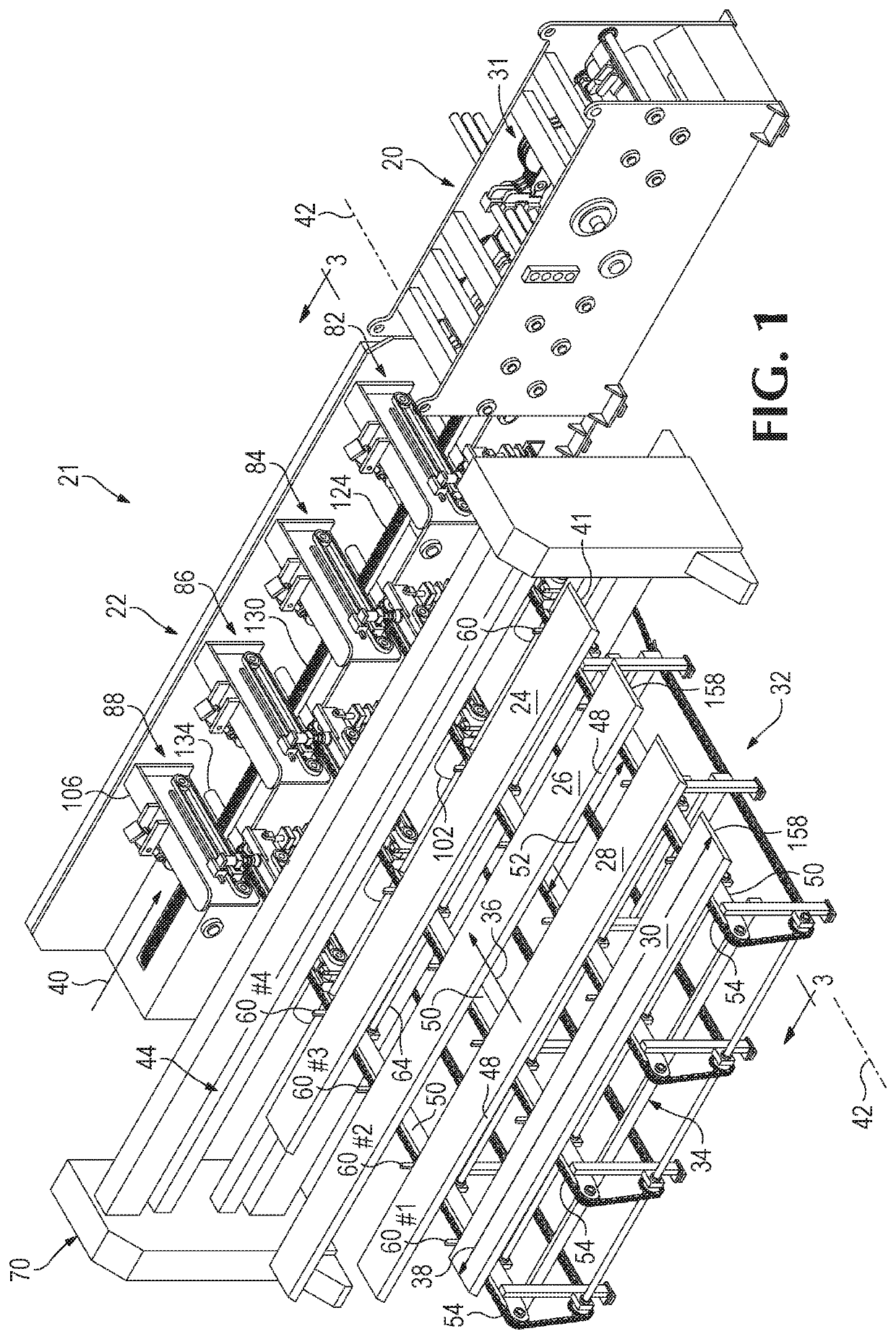
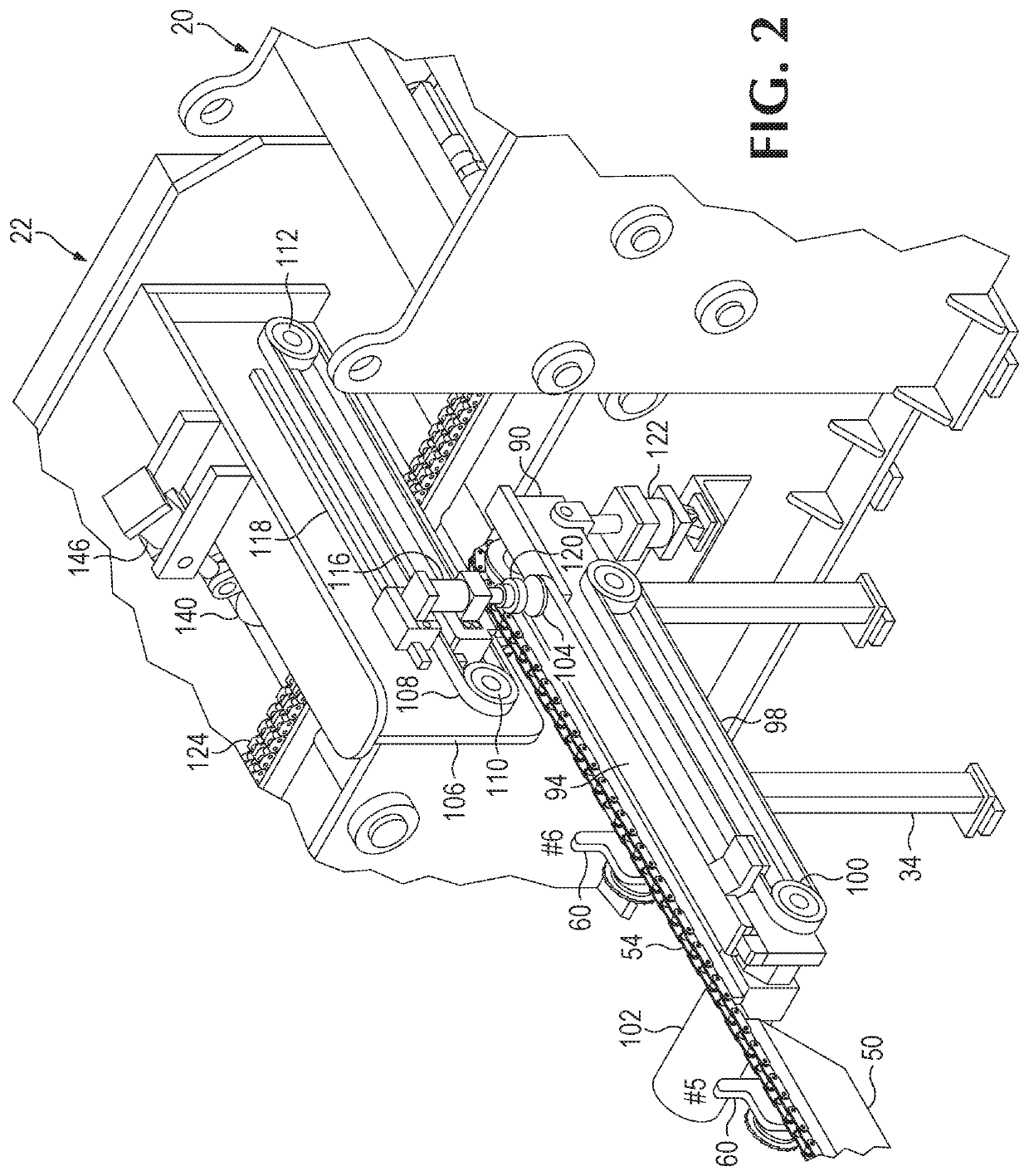
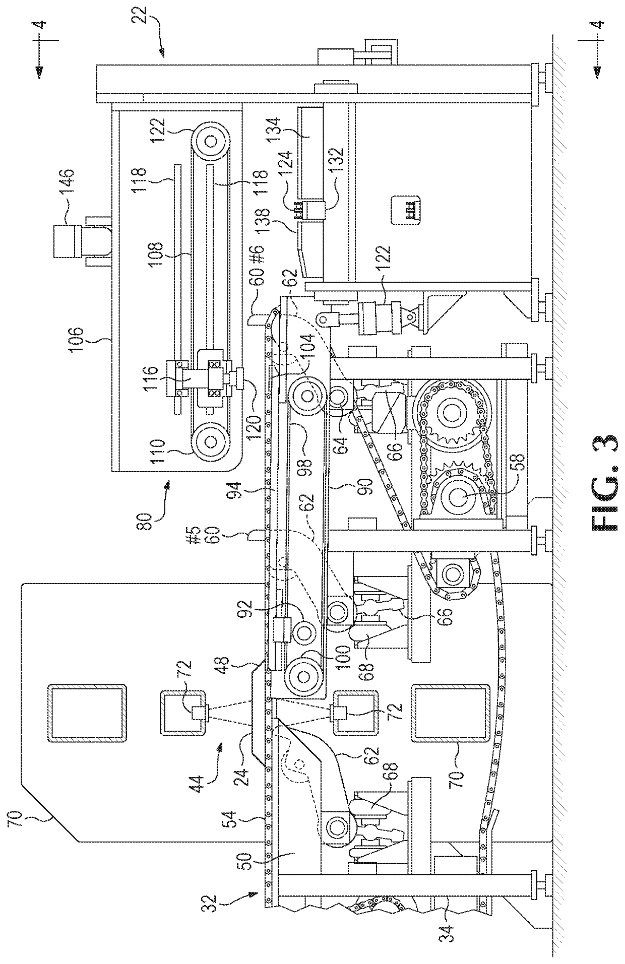
[0053]Referring first to FIGS. 1-4 of the drawings that form a part of the disclosure herein, an edger 20 and an edger feed apparatus 21 that includes an edger infeed mechanism 22 arranged to deliver a flitch of wood 24, 26, 28, or 30, etc. into the edger 20. The edger 20 includes a set of edger saws 31 that are spaced apart from each other so as to produce a board or set of boards from a flitch 24, etc., while removing bark-covered wane portions of the flitch that are of no commercial value as lumber. Unless explicitly stated, edger feed apparatus 21 may additionally, or alternatively, include one or more components of one or more other edger feed apparatus of the present disclosure. Edger infeed mechanism 22 is controlled and operated by various sensors and servo systems shown schematically in FIG. 19.

[0054]Edger feed apparatus 21 further includes a scanner and carriage assembly 32, that also may be called a feedline or carriage assembly, has a structural frame 34 oriented to deli...


PUM

PropertyMeasurementUnit
sizeaaaaaaaaaa
heightaaaaaaaaaa
distanceaaaaaaaaaa

Abstract

An edger feed apparatus and method of feeding flitches into an edger are disclosed. The flitches are positioned with minimal spacing between successive flitches and with flitches positioned and the edger adjusted so as to yield a maximum value of lumber from each flitch. The edger feed apparatus may include a fetcher assembly to hold a second flitch in an edger ready position while a portion of the first flitch is directed below on an edger infeed mechanism being transported to the edger. The fetcher assembly releases the second flitch on to the edger infeed mechanism when the first flitch has moved clear from beneath the edger ready position. The edger feed apparatus additionally includes a scanner system for creating and storing a digital three-dimensional model of each flitch for determining a sawing solution to be implemented by the edger.

Description

CROSS-REFERENCE TO RELATED APPLICATIONS[0001]This application is a continuation-in-part of U.S. patent application Ser. No. 16 / 438,005 filed on Jun. 11, 2019 and entitled “Method and Apparatus for Feeding an Edger,” which claims the benefit of U.S. Provisional Patent Application Ser. No. 62 / 683,509 filed on Jun. 11, 2018 and entitled “Method and Apparatus for Feeding an Edger.” The complete disclosures of the above applications are hereby incorporated by reference for all purposes.BACKGROUND OF THE INVENTION[0002]The present invention relates to processing wood products, and in particular to apparatus and a method for feeding flitches into an edger so as to optimize production of marketable lumber from the flitches.[0003]When a log is sawed in the process of producing lumber a cant or cants are produced from the central portion of the log by removing slabs and flitches from sides of the log, usually in a way to maximize the marketable amount of lumber that can be produced from the c...

Claims


Application Information

Patent Timeline
Patent Type & Authority Applications(United States)
IPC IPC(8): B23D59/00B27B29/02B27B31/02
CPCB27B31/02B27B29/02B23D59/008B27B5/04B27B31/06
Inventor MITCHELL, RORY MATTHEWMITCHELL, ALLISON NICOLE
Owner SALEM EQUIP
Why Eureka
Try Eureka