
Protective cover and unmanned aerial vehicle

Inactive Publication Date: 2020-07-09
SZ DJI TECH CO LTD
View PDF0 Cites 3 Cited by
  • Summary
  • Abstract
  • Description
  • Claims
  • Application Information

AI Technical Summary

Benefits of technology

The patent text describes a problem with current gimbal cameras where the protection mechanism can be easily lost and the user experience is poor during disassembly and assembly. The technical effect is to develop a more robust and easily usable protection mechanism for gimbal cameras.

Problems solved by technology

In a process of transporting and carrying the UAV, there are inevitable vibration and shock.
If the gimbal camera is not supported and protected, the gimbal camera is vulnerable to bumps, which may result in poor operations and even damages.
However, components of the protection mechanism are scattered and easily lost after repeated uses.
During a disassembly and assembly of the gimbal camera, the multi-component protection mechanism is cumbersome to use, and a user experience is poor.

Method used


Image

  • Protective cover and unmanned aerial vehicle
  • Protective cover and unmanned aerial vehicle
  • Protective cover and unmanned aerial vehicle

Examples


Embodiment Construction

[0019]The technical solutions in the embodiments of the present disclosure will be described below with reference to the accompanying drawings. Obviously, the described embodiments are part of the embodiments of the present disclosure, but not all the embodiments. Based on the described embodiments of the present disclosure, other embodiments acquired by those skilled in the art without creative efforts shall fall within the protection scope of the present disclosure.

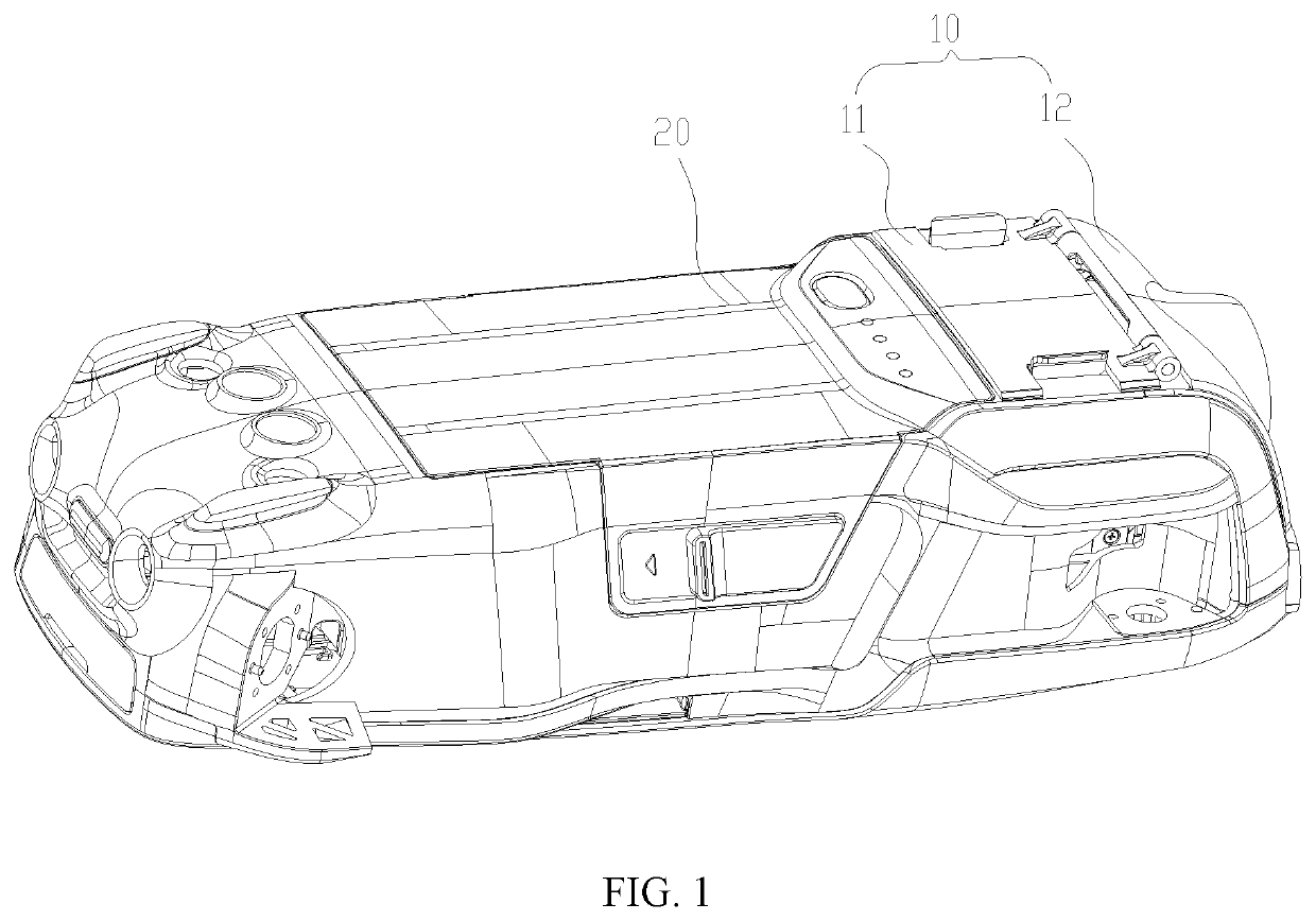
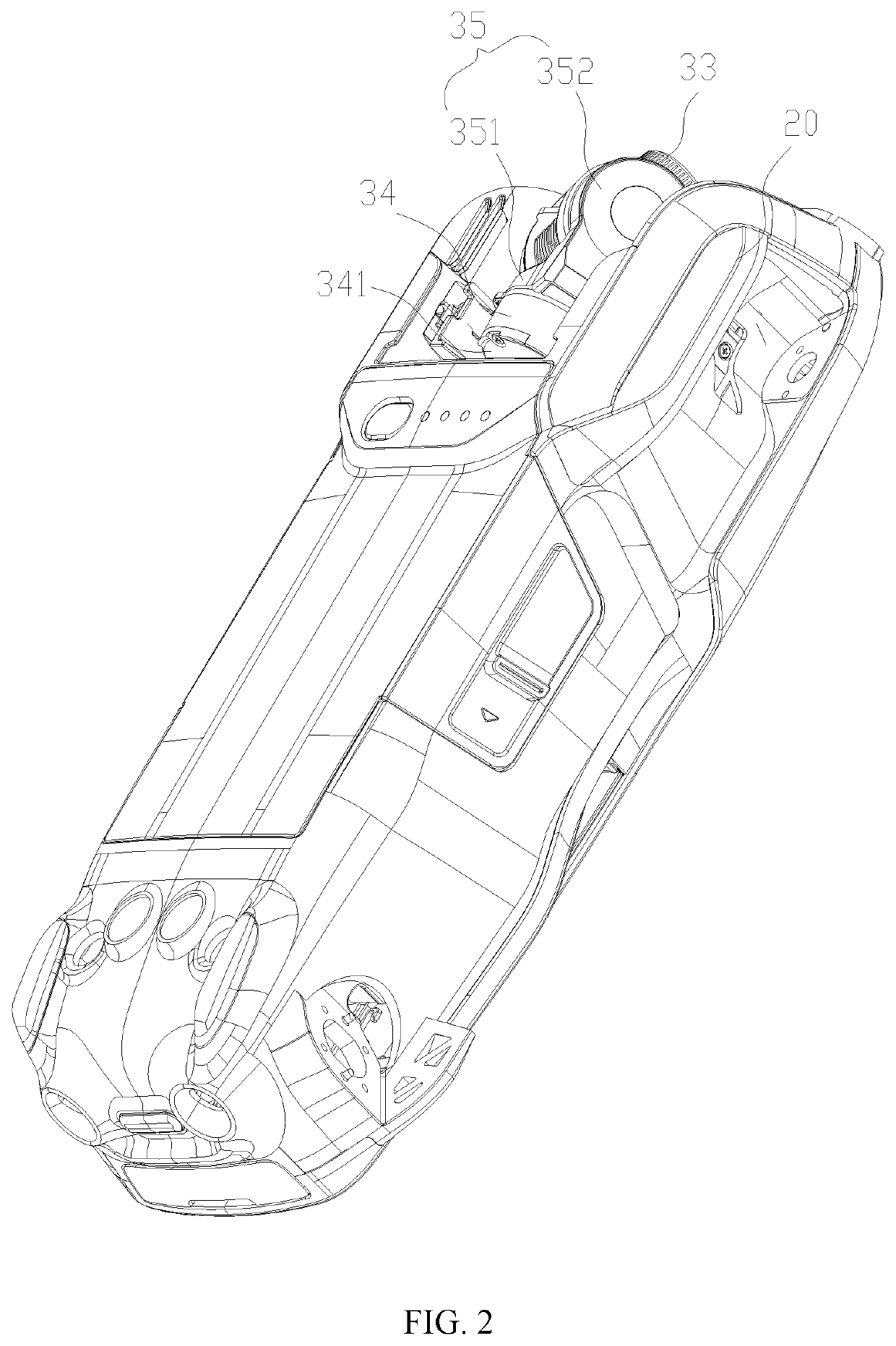
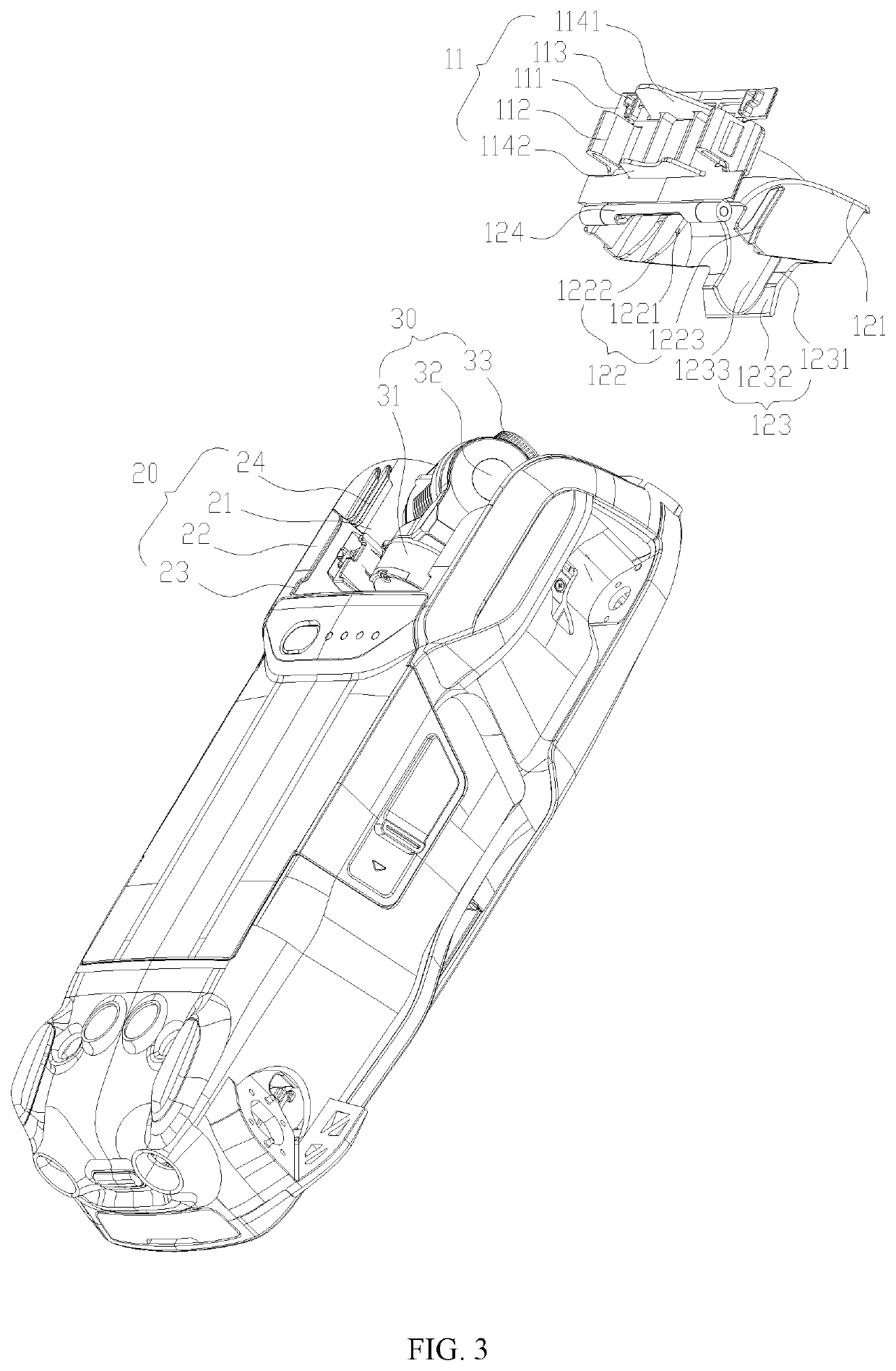
[0020]As shown in FIGS. 1, 2 and 3, a UAV includes a fuselage 20, a gimbal camera 30, and a protective cover 10 assembled on the fuselage 20. The gimbal camera includes a driving device 34, an imaging device 33, and a gimbal frame 35 connecting the driving device 34 and the imaging device 33. The gimbal camera includes a gimbal with a one-axis, two-axis, or three-axis head. The fuselage 20 includes a recessed part 21 in which a storage space is formed. The storage space is similar to a trapezoidal space, which is surrou...


PUM


Abstract

Protective cover for a gimbal camera of an unmanned aerial vehicle (UAV) and UAV are provided. The protective cover includes a stopper slidingly connected to the UAV and a locking member rotatably connected to the stopper. The locking member is configured to be locked to the UAV such that the stopper and the locking member are fixed to the UAV. The locking member is closed with the stopper to at least partially cover the gimbal camera.

Description

CROSS-REFERENCES TO RELATED APPLICATIONS[0001]This application is a continuation of International Application No. PCT / CN2017 / 104575, filed on Sep. 29, 2017, the entire content of which is incorporated herein by reference.FIELD OF THE DISCLOSURE[0002]The present disclosure generally relates to the field of electronic equipment technology and, more particularly, relates to a protective cover and an unmanned aerial vehicle.BACKGROUND[0003]An unmanned aerial vehicle (UAV) is equipped with a gimbal camera, which protrudes from a fuselage surface of the UAV and has a plurality of degrees of freedom adapt to adjust shooting angle thereof. The gimbal camera includes a yaw axis, a pitch axis and a roll axis. By controlling rotational and translational movements of the yaw axis, the pitch axis, and the roll axis, the gimbal camera can make stable shootings during a UAV flight and shooting angles are wide.[0004]The gimbal camera and the UAV are in a cantilever beam structure. In a process of t...

Claims


Application Information

Patent Timeline
IPC IPC(8): G03B17/56B64C39/02B64D47/08
CPCB64D47/08B64C2201/027B64C39/024G03B17/56B64U2101/30B64U20/87G03B17/561G03B17/04G03B15/006B64U10/13
Inventor HUANG, TONGYAOFENG, JIANGANGLIAO, RANXU, HUI
Owner SZ DJI TECH CO LTD
Learn More