
Utilizing Vision Systems at a Wellsite

Inactive Publication Date: 2020-07-16
SCHLUMBERGER TECH CORP
View PDF0 Cites 13 Cited by
  • Summary
  • Abstract
  • Description
  • Claims
  • Application Information

AI Technical Summary

Benefits of technology

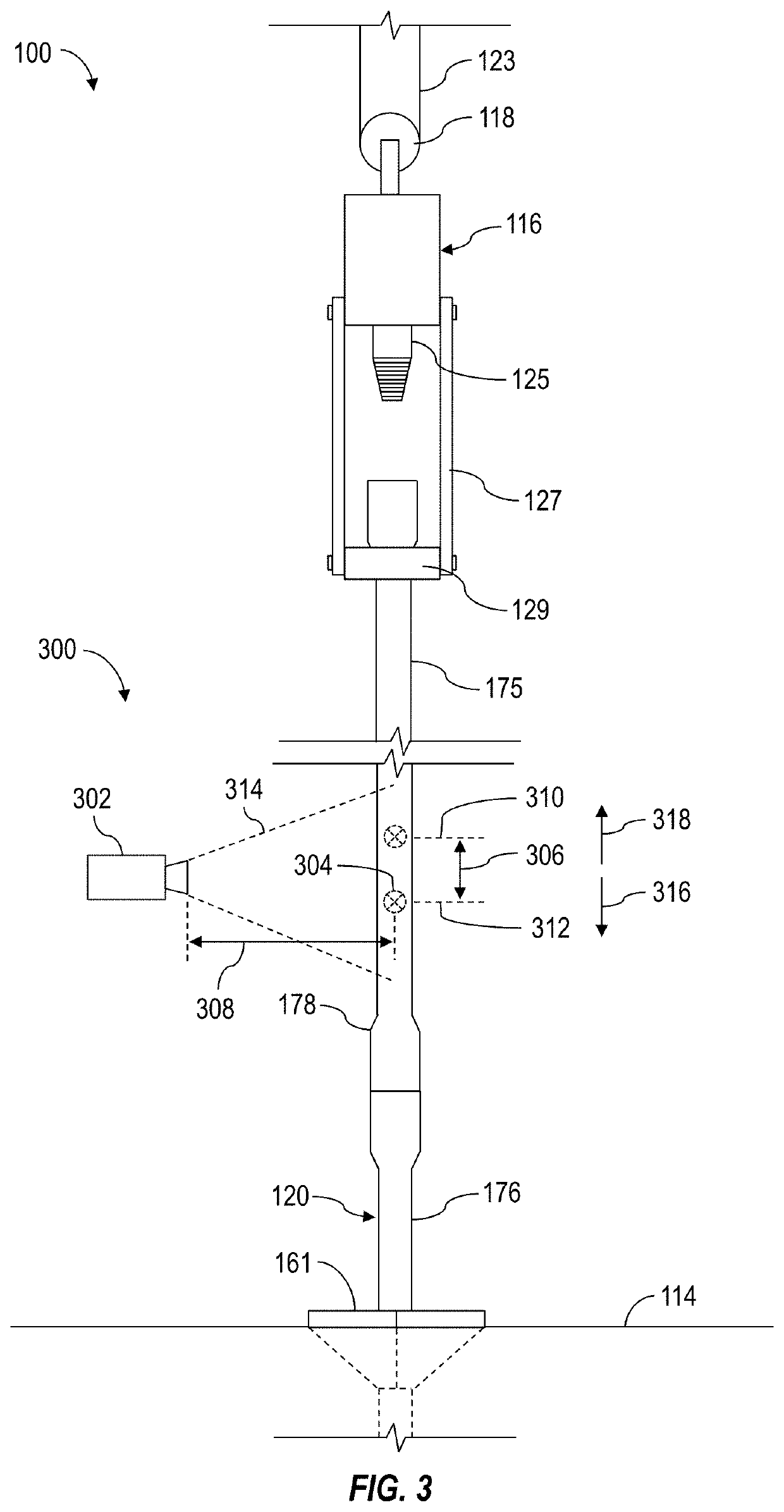
The present patent introduces various methods for using video cameras to monitor and determine the orientation and position of downhole tubulars in oil and gas wells. These methods include using geometric patterns on the outer surface of the tubulars for determining azimuthal orientation, monitoring alignment between the pin end of an upper tubular and the box end of a lower tubular, measuring wear on drill bits, and monitoring safety regulation compliance. These methods can be used to improve the accuracy and efficiency of wellbore drilling and wellbore construction operations.

Problems solved by technology

However, images (or video frames) of the wellsite equipment captured by the video cameras also comprise information indicative of certain physical characteristics and / or operational status of such wellsite equipment that may not be recognized or otherwise appreciated by the wellsite operators viewing the images on a video monitor.

Method used


Image

  • Utilizing Vision Systems at a Wellsite
  • Utilizing Vision Systems at a Wellsite
  • Utilizing Vision Systems at a Wellsite

Examples


Embodiment Construction

[0040]It is to be understood that the following disclosure provides many different embodiments, or examples, for implementing different features of various embodiments. Specific examples of components and arrangements are described below to simplify the present disclosure. These are, of course, merely examples and are not intended to be limiting. In addition, the present disclosure may repeat reference numerals and / or letters in the various examples. This repetition is for simplicity and clarity, and does not in itself dictate a relationship between the various embodiments and / or configurations discussed.

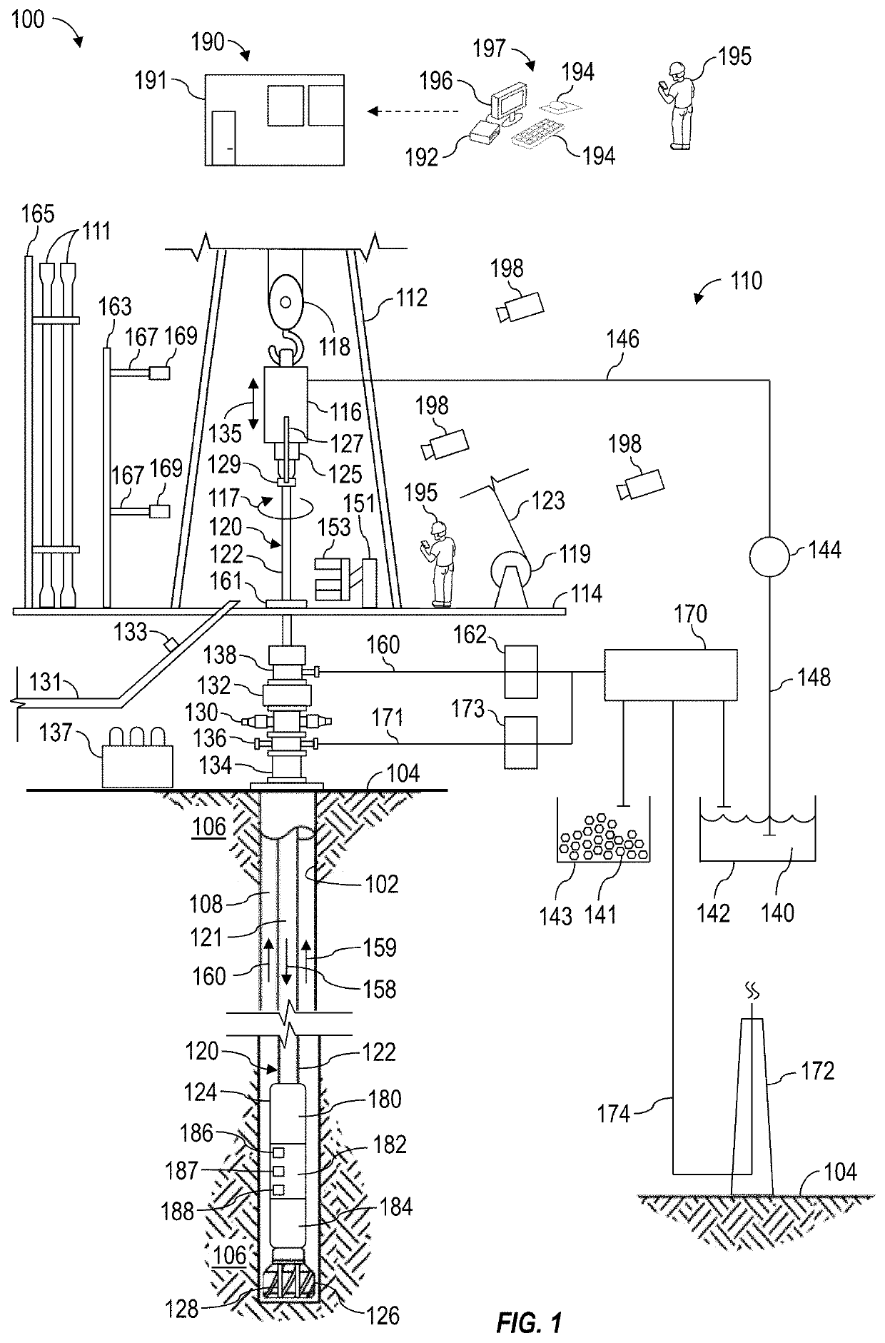
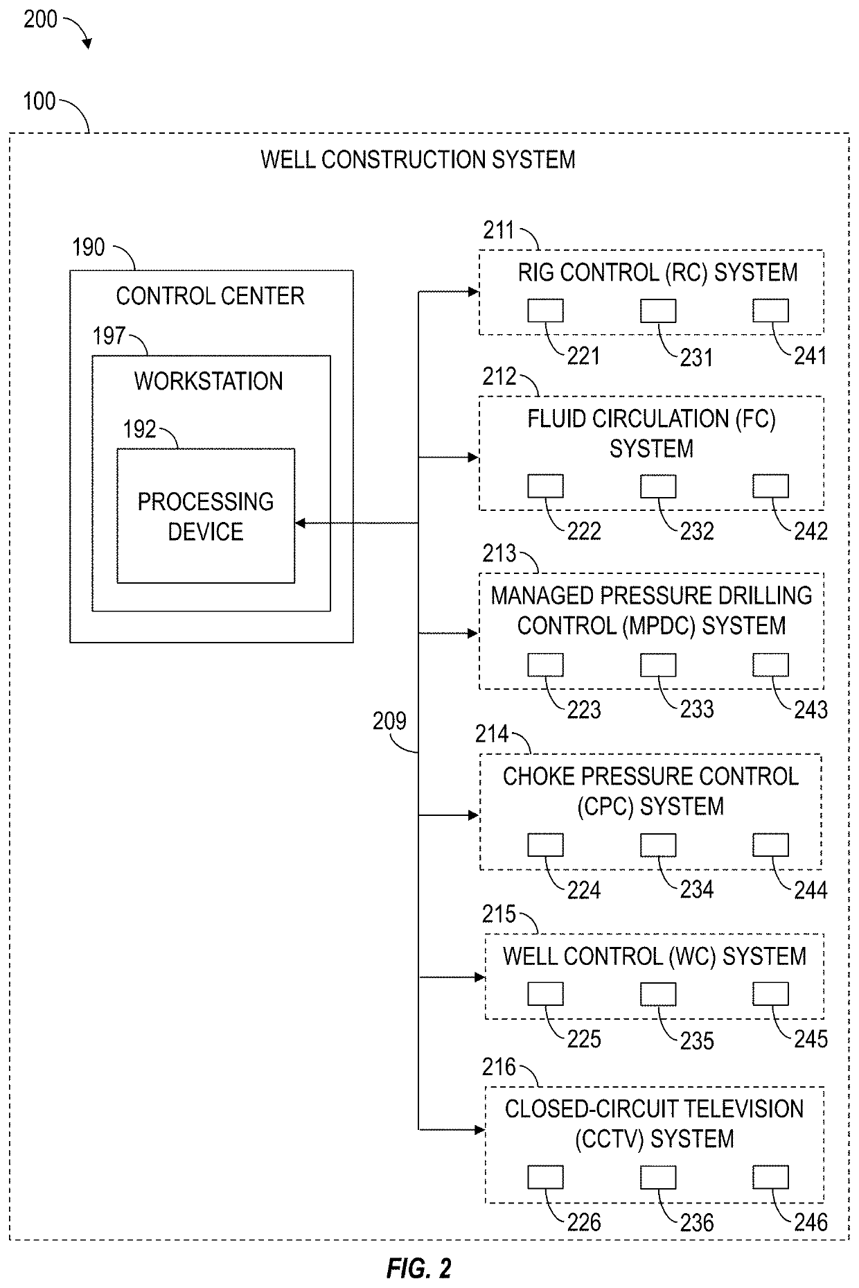
[0041]Systems and methods (e.g., processes, operations) according to one or more aspects of the present disclosure may be utilized or otherwise implemented in association with an automated well construction system at an oil and gas wellsite, such as for constructing a wellbore to obtain hydrocarbons (e.g., oil and / or gas) from a subterranean formation. However, one or more aspects o...


PUM


Abstract

Utilizing vision systems at a wellsite, which may include operating a video camera to generate a video signal comprising images of one or more pieces of equipment or components and receiving the video signal by a processing system, which may then process the images to determine physical and / or operational characteristics associated with the one or more pieces of equipment in the images. The video signal may contain images of a crown block and / or a drawworks of a hoisting system at an oil and gas drill rig. The processing system may then process the video signal to determine when a traveling block of the hoisting system is within a threshold distance from the crown block.

Description

BACKGROUND OF THE DISCLOSURE[0001]Wells are generally drilled into the ground or ocean bed to recover natural deposits of oil, gas, and other materials that are trapped in subterranean formations. Well construction operations (e.g., drilling operations) may be performed at a wellsite by a drilling system having various surface and subterranean equipment operating in a coordinated manner. The wellsite equipment may be grouped into various subsystems, wherein each subsystem performs a different operation controlled by a corresponding local and / or a remotely located controller.[0002]A video system, such as a CCTV system, comprising a plurality of video cameras distributed at various locations at a wellsite is utilized to display selected wellsite equipment on one or more video monitors to facilitate viewing of the wellsite equipment and progress of the well construction operations. For example, a human wellsite operator (e.g., a driller) may utilize the video system to visually monitor...

Claims


Application Information

Patent Timeline
IPC IPC(8): E21B44/00E21B19/16
CPCE21B44/00E21B19/165E21B19/02E21B19/08E21B2200/22G01B11/022G01B11/27G06T7/60G06T2207/10016G06T2207/30164H04N7/18
Inventor PARMESHWAR, VISHWANATHANSINGH, MANATWANG, RICHARD
Owner SCHLUMBERGER TECH CORP
Learn More