

Numerical control system
a control system and numerical control technology, applied in the direction of program control, electric programme control, instruments, etc., can solve the problems of tool wear, vibration, tool deflection, etc., and achieve the effect of reducing the number of control systems
- Summary
- Abstract
- Description
- Claims
- Application Information
AI Technical Summary
Benefits of technology
Problems solved by technology
Method used
Image

Examples
embodiment 1
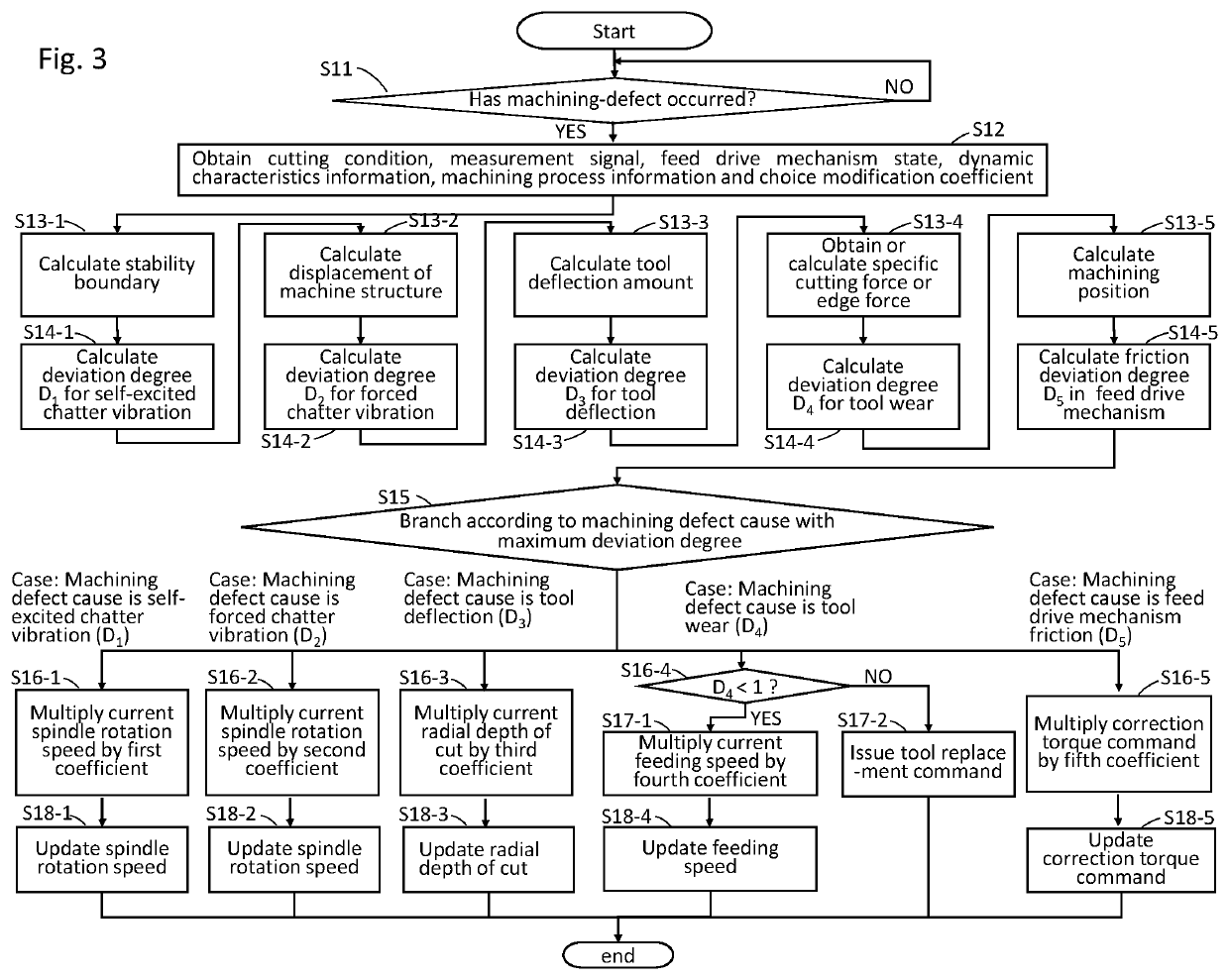
[0035]In the description of the present invention, causes of machining defects detected are called as machining defect causes. To be concrete, the machining defect causes include chatter vibrations, tool deflections, tool wear, and friction in feed drive mechanism, which will be described below.
[0036]The chatter vibrations here are vibrations which occur during cutting machining. The chatter vibrations may lower the machining accuracy and harm the life span of the tool. The chatter vibration is classified into self-excited chatter vibrations and forced chatter vibrations. The self-excited chatter vibrations are exponentially amplified by a cutting process itself. The forced chatter vibrations are generated by vibrating the machine structure with the cutting force.
[0037]The tool deflections are phenomena in which the tool edge is bent by receiving a cutting force, lowering the machining accuracy.
[0038]The tool wear is a phenomenon that the cutting edge of the tool repeatedly touches ...
embodiment 2
[0144]In Embodiment 1, it has been described that after choosing a machining defect cause, the correction amount is calculated by multiplying the control amount corresponding to the machining defect cause by a coefficient. In the present embodiment 2, description will be made about a configuration in which the correction-amount calculation unit switches rules for changing the control according to the determination results on a machining defect cause.
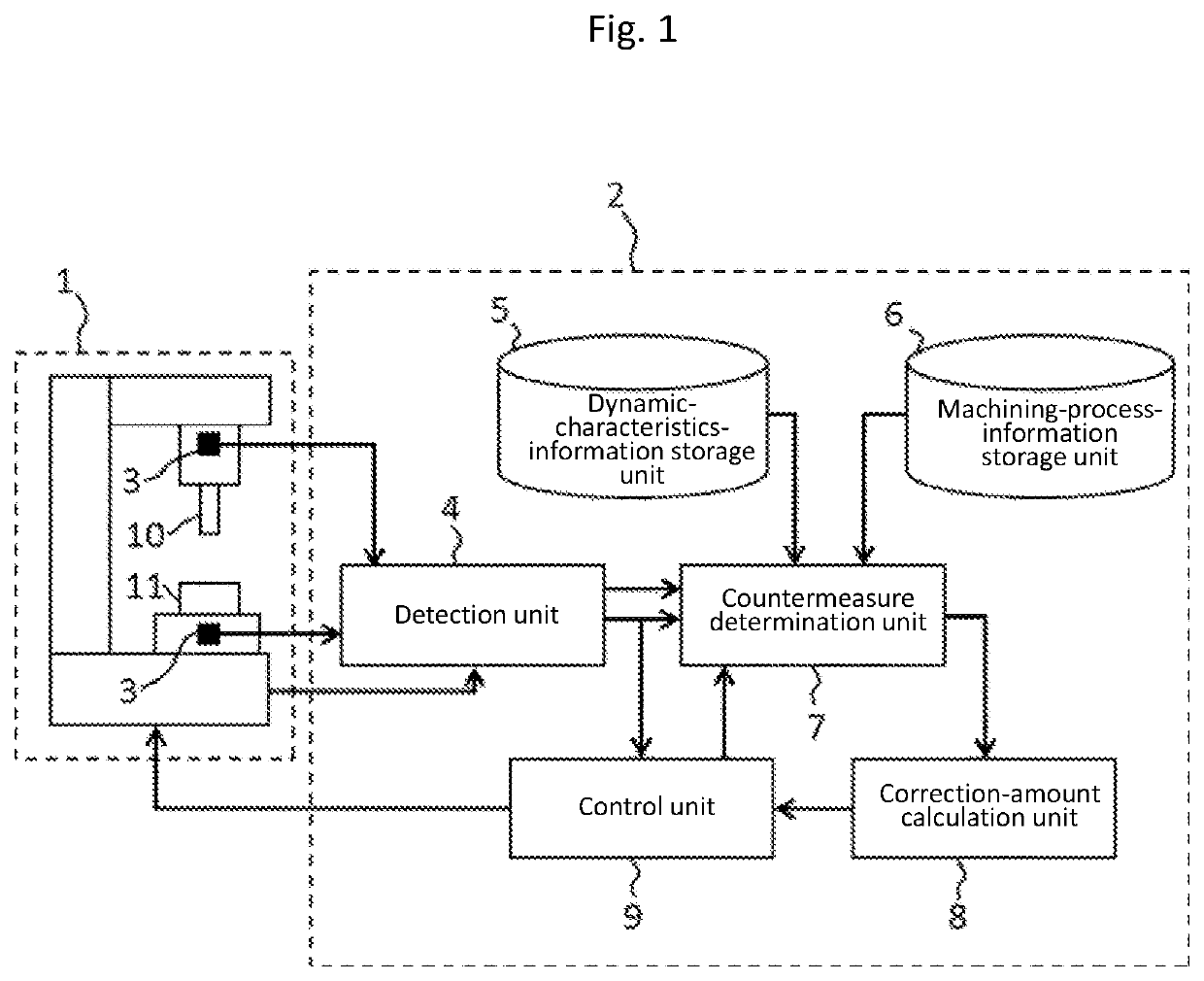
[0145]FIG. 7 is a block diagram of a numerical control system according to Embodiment 2 of the present invention. Note that, in FIG. 7, components identical or equivalent to those of Embodiment 1 shown in FIG. 1 are given the same symbols. Here, description will be made focusing on parts characterizing the present embodiment 2.
[0146]In the same way as the countermeasure determination unit 7 according to Embodiment 1 does, a countermeasure determination unit 7a receives the feed drive mechanism state, the dynamic characteristics informati...
embodiment 3
[0165]In the description of Embodiment 1 and 2, a machining defect cause is determined on the basis of deviation degrees. In the present embodiment 3, description will be made about a configuration in which selection of a machining defect cause is corrected on the basis of the worker's input in addition to deviation degrees.
[0166]FIG. 10 is a block diagram of a numerical control system 2b according to Embodiment 3 of the present invention. Note that, in FIG. 10, components identical or equivalent to those shown in FIG. 7 of Embodiment 1 are given the same symbols. Hence, here, description will be made focusing on parts relating to the present embodiment 3.
[0167]The numerical control system 2b includes the detection unit 4, the dynamic-characteristics-information storage unit 5, the machining-process-information storage unit 6, a countermeasure determination unit 7b, the correction-amount calculation unit 8, the control unit 9 and an input unit 27. The machine tool 1 includes the sen...
PUM
 Abstract
Description
Claims
Application Information