Robot joint structure and robot with backlash reduction mechanism

a robot and backlash reduction technology, applied in the field of robots, can solve the problems of difficult adjustment of backlash between the motor-side gear and the mating gear, affecting etc., and achieve the effect of reducing backlash and improving the trajectory accuracy of the robo

Pending Publication Date: 2020-07-23
FANUC LTD
View PDF19 Cites 4 Cited by
  • Summary
  • Abstract
  • Description
  • Claims
  • Application Information

AI Technical Summary

Benefits of technology

[0015]Therefore, even when an auxiliary bearing is used for the motor of the robot joint shaft, there is a need for a technique for improving the trajectory accuracy of the robot by reducing the backlash between the motor-side gear and the mating gear.

Problems solved by technology

In addition, since gravity may not act on the gears of other joint shafts capable of turning about the vertical axis, for example, the fourth to sixth shafts of the vertical articulated robot, backlash existing on these joint shafts may also affect the robot trajectory accuracy.
On the other hand, when the distance from a motor to a speed reduction gear mechanism is long and a motor shaft is extended, an auxiliary bearing may be mounted in order to reduce the load on the motor shaft and ensure rigidity, but since the position of the rotational shaft of the gear mounted on the motor shaft is fixed by the auxiliary bearing, it has been difficult to adjust the backlash between the motor-side gear and the mating gear.

Method used


Image

  • Robot joint structure and robot with backlash reduction mechanism
  • Robot joint structure and robot with backlash reduction mechanism
  • Robot joint structure and robot with backlash reduction mechanism

Examples


Embodiment Construction

[0024]Embodiments of the present disclosure will be described below in detail with reference to the accompanying drawings. In each drawing, the same or similar components are designated by the same or similar reference numerals. Furthermore, the embodiments described below do not limit the technical scope of the invention and the meaning of the terms described in the claims.

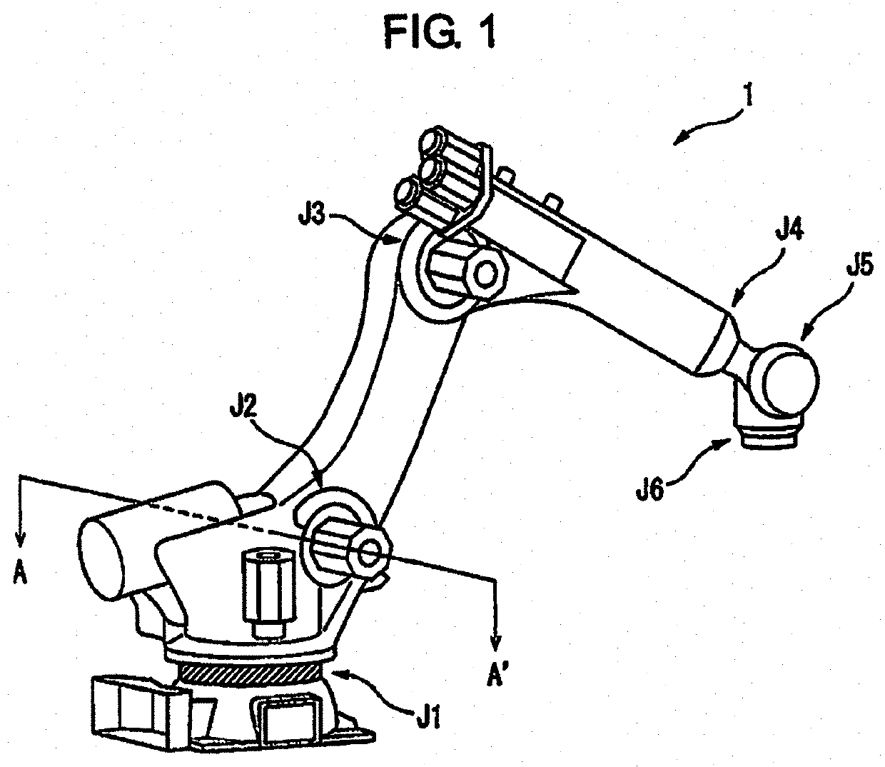
[0025]FIG. 1 is a perspective view of a robot 1 according to the present embodiment. Although the robot 1 of the present example is an industrial robot, particularly a vertical articulated robot, it should be noted that the present invention is not limited to this and can be applied to, for example, a horizontal articulated robot or the like. The robot 1 is used, for example, in a laser application, a sealing application, or the like, and various end effectors (not illustrated) are attached to the robot tip 10. As illustrated by reference numerals J1 to J6, the robot 1 includes six joint shafts. Since the first s...


PUM


Abstract

A robot joint structure includes a motor configured to be used for a robot joint shaft capable of turning about a vertical axis, a motor-side gear mounted on a shaft of the motor, an auxiliary bearing configured to axially support the shaft supplementally, an adapter configured to integrate the motor, the motor-side gear, and the auxiliary bearing, and a moving mechanism configured to move a unit structure integrated by the adaptor in a radial direction of the motor such that the motor-side gear approaches a mating gear meshing with the motor-side gear.

Description

BACKGROUND OF THE INVENTION1. Field of the Invention[0001]The present invention relates to a robot, and particularly to a robot joint structure and a robot with a backlash reduction mechanism.2. Description of the Related Art[0002]In a laser application, a sealing application, or the like that performs processing while a robot is operating, the trajectory accuracy of the robot is directly transferred to the product accuracy, so that a high trajectory accuracy is required for the robot.[0003]In many industrial robots such as vertical articulated robots and horizontal articulated robots, a drive method in which torque output from a servomotor is amplified by a speed reduction mechanism is adopted, but backlash existing in the speed reduction mechanism causes an error in the rotation between the motor shaft and the output shaft, which degrades the trajectory accuracy of the robot. As a related art for removing, reducing or adjusting such backlash, for example, Patent Documents 1 to 10 ...

Claims


Application Information

Patent Timeline
Patent Type & Authority Applications(United States)
IPC IPC(8): B25J9/10F16H57/12B25J9/04
CPCB25J9/103B25J9/042F16H57/12F16H2057/125B25J17/02B25J9/126B25J9/102F16H2057/0213F16H2057/0222F16H57/039
Inventor MURAKAMI, KUNIHIKO
Owner FANUC LTD
Why Eureka
Try Eureka