Movable display device

a display device and movable technology, applied in the field of display devices, can solve the problems of difficult assembly and disassembly of large led display screens, occupies a very large space, and cannot be folded, so as to achieve the effect of increasing convenience and practicality

Active Publication Date: 2020-07-23
HARVATEK CORPORATION
View PDF0 Cites 5 Cited by
  • Summary
  • Abstract
  • Description
  • Claims
  • Application Information

AI Technical Summary

Benefits of technology

[0009]One of the advantages of the present disclosure is that the movable display device has an increased convenience and practicality by the technical features of “the carrying module includes a carrier unit, a base unit disposed on the carrier unit, and a plurality of positioning units disposed on the carrier unit,”“the lifting module is disposed on the base unit,”“the frame module includes a primary frame unit movably connected to the positioning units and a plurality of secondary frame units movably connected to the primary frame unit, the primary frame unit has a connecting portion connected to the lifting module, and the secondary frame units are respectively located at two sides of the primary frame unit,”“the display module includes a primary display unit disposed on the primary frame unit and a plurality of secondary display units respectively disposed on the secondary frame units,” and “when the movable display device is at a folded state, each of the secondary frame units has a first predetermined angle relative to the primary frame unit, the connecting portion is close to the carrier unit, and the primary display unit and the secondary display units are at a first position.”

Problems solved by technology

Such a large LED display screen is difficult to be assembled and disassembled.
In addition, the large LED display screen cannot be folded and thus occupies a very large space when not in use, and cannot be raised and lowered to fit different needs.

Method used


Image

  • Movable display device
  • Movable display device
  • Movable display device

Examples


first embodiment

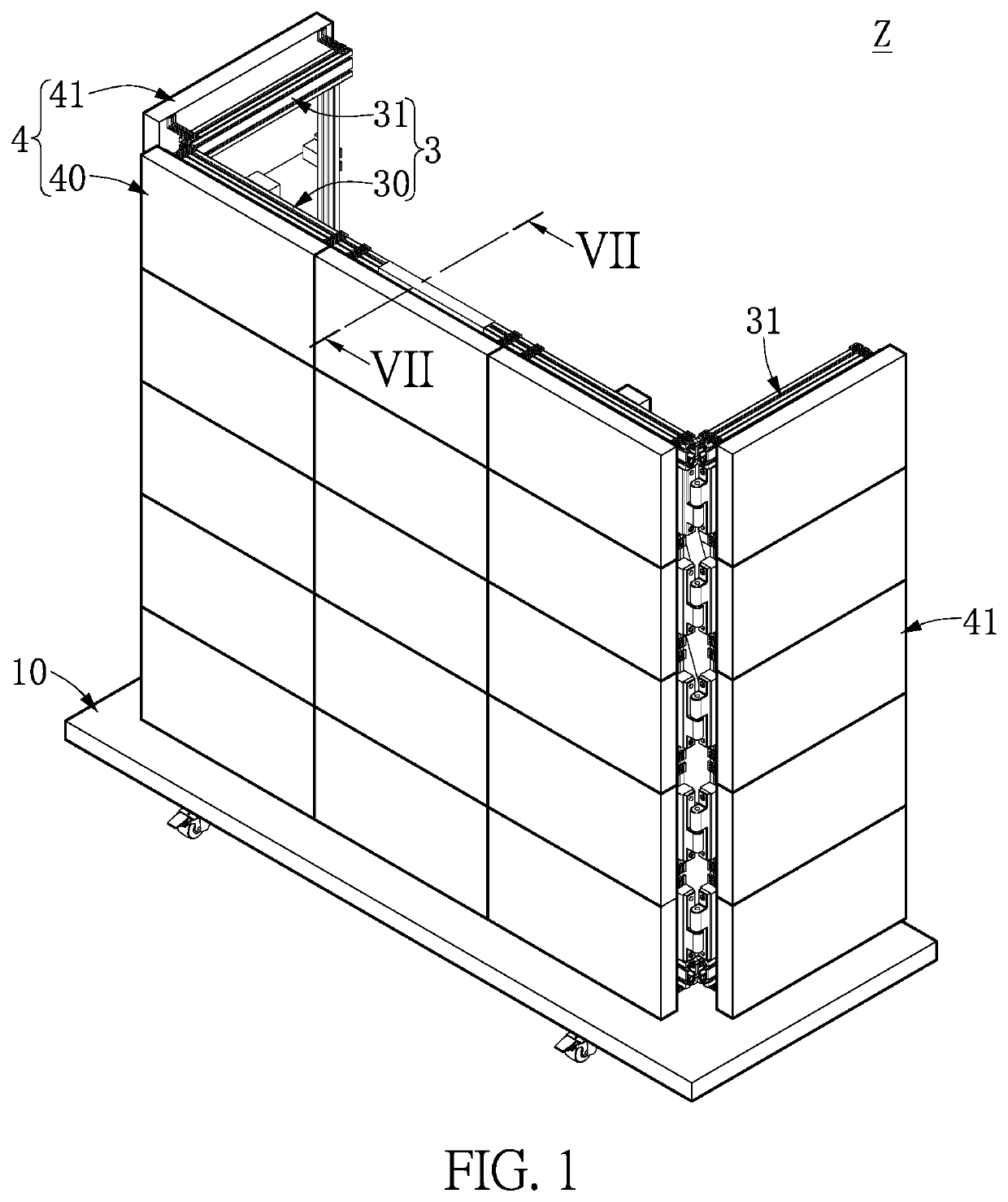
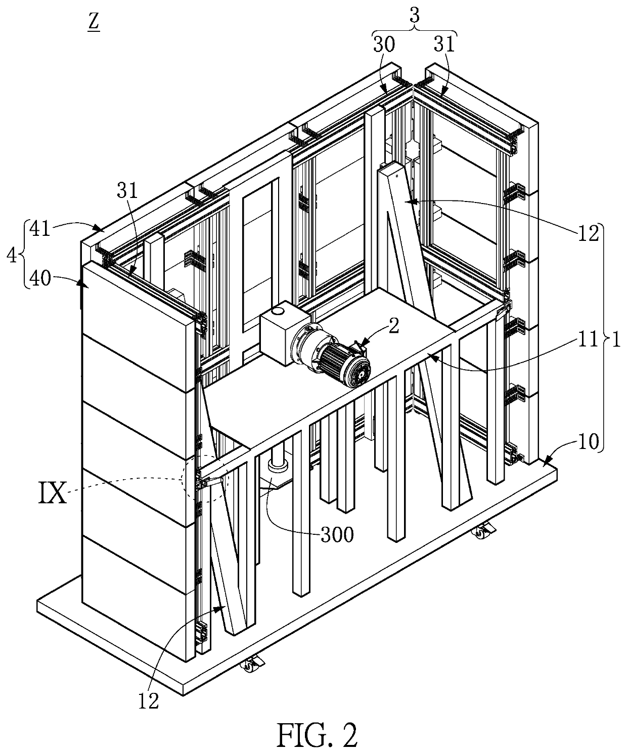
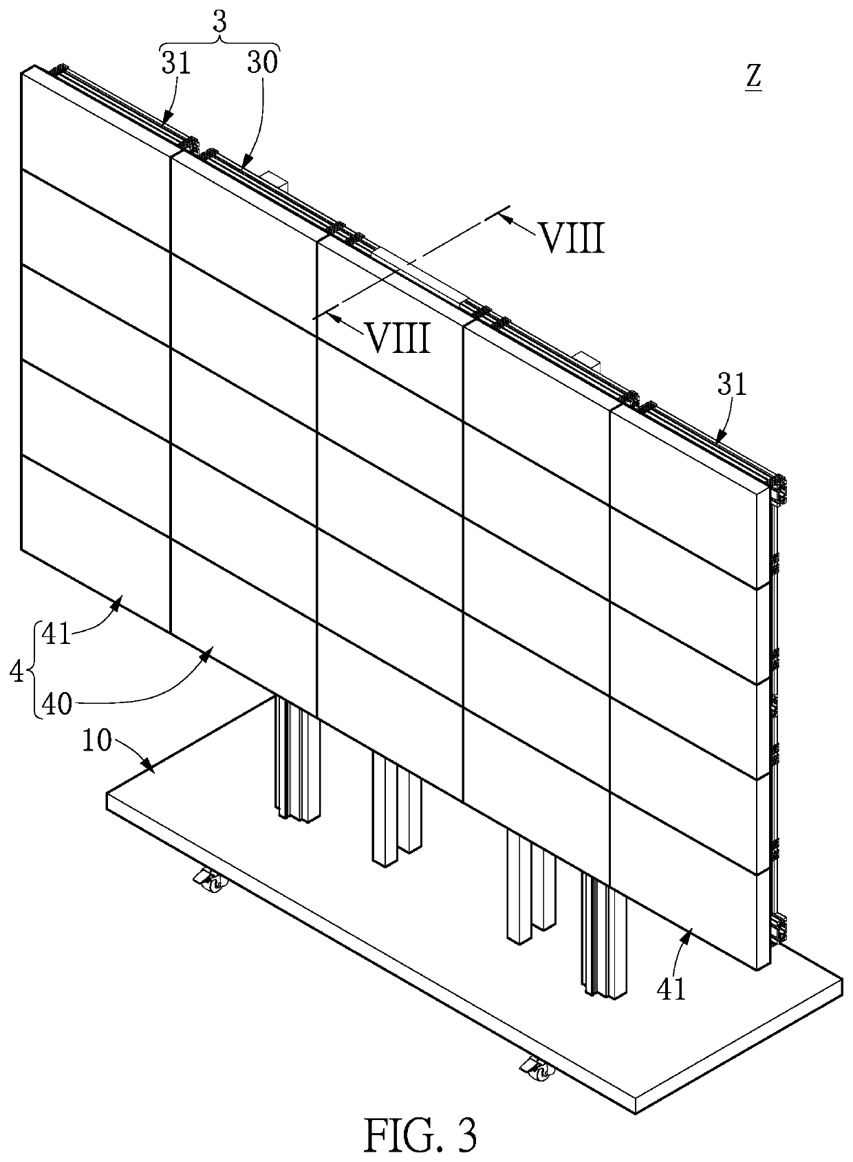
[0026]FIG. 1 to FIG. 6 are respectively a perspective view showing a movable display device according to a first embodiment of the present disclosure in a folded state, another perspective view showing the movable display device in the folded state, a perspective view showing the movable display device in an expanded state, another perspective view showing the movable display device in the expanded state, a top view showing the movable display device in the folded state, and a top view showing the movable display device in the expanded state. As shown in FIG. 1 to FIG. 6, the movable display device Z that includes a carrying module 1, a lifting module 2, a frame module 3 and a display module 4. The carrying module 1 includes a carrier unit 10, a base unit 11 disposed on the carrier unit 10, and a plurality of positioning units 12 disposed on the carrier unit 10. The lifting module 2 is disposed on the base unit 11. The frame module 3 includes a primary frame unit 30 movably connecte...

second embodiment

[0034]FIG. 7 to FIG. 9 are respectively a cross-sectional view taken along line VII-VII of FIG. 1, a cross-sectional view taken along line VIII-VIII of FIG. 3 and an enlarged view of a portion IX in FIG. 2. As shown in FIG. 7 to FIG. 9, which is to be read in conjunction with FIG. 1 to FIG. 6, the movable display device Z of the present embodiment has the same elements as that of the first embodiment, and the actions of such elements are similar as described in the first embodiment and will not be reiterated herein. It should be noted that, in the present embodiment, the connecting portion 300 is driven by the lifting module 2 to move the primary frame unit 30 and the secondary display units 31 together with the primary display unit 40 and the secondary display units 41 from the first position to the second position.

[0035]For example, in the movable display device Z of the present embodiment, the connecting portion 300 of the primary frame unit 30 can be driven by the lifting module...

third embodiment

[0040]FIG. 10 to FIG. 12 are respectively a schematic view of a movable display device according to a third embodiment of the present disclosure in the folded state, a schematic view showing an assembled casing module of the movable display device, and a schematic view of the movable display device in the expanded state. As shown in FIG. 10 to FIG. 12, which is to be read in conjunction with FIG. 1 to FIG. 9, the movable display device Z of the present embodiment has the same elements as that of the first embodiment, and the actions of such elements are similar as described in the above embodiments and will not be reiterated herein. It should be noted that, in the present embodiment, the movable display device Z can further include a casing module 5 that includes a plurality of upper casings 50 and a lower casing 51. When the casing module 5 is at an assembled state, the lower casing 51 is detachably connected to the carrier unit 10, and the upper casings 50 and the lower casing 51 ...


PUM


Abstract

A movable display device includes a carrying module, a lifting module, a frame module and a display module. The carrying module includes a carrier unit, a base unit disposed on the carrier unit, and a plurality of positioning units disposed on the carrier unit. The lifting module is disposed on the base unit. The frame module includes a primary frame unit movably connected to the positioning units and a plurality of secondary frame units movably connected to the primary frame unit. The primary frame unit has a connecting portion connected to the lifting module. The secondary frame units are respectively located at two sides of the primary frame unit. The display module includes a primary display unit disposed on the primary frame unit and a plurality of secondary display units respectively disposed on the secondary frame units.

Description

CROSS-REFERENCE TO RELATED PATENT APPLICATION[0001]This application claims priority from the U.S. Provisional Patent Application Ser. No. 62 / 795,413 filed Jan. 22, 2019, which application is incorporated herein by reference in its entirety.[0002]Some references, which may include patents, patent applications and various publications, may be cited and discussed in the description of this disclosure. The citation and / or discussion of such references is provided merely to clarify the description of the present disclosure and is not an admission that any such reference is “prior art” to the disclosure described herein. All references cited and discussed in this specification are incorporated herein by reference in their entireties and to the same extent as if each reference was individually incorporated by reference.FIELD OF THE DISCLOSURE[0003]The present disclosure relates to a display device, and more particularly to a movable display device capable of being assembled and easily move...

Claims


Application Information

Patent Timeline
Patent Type & Authority Applications(United States)
IPC IPC(8): G06F3/14G06F1/16
CPCG06F3/1446G06F1/1601G06F1/1641G06F2200/1612G09F9/302G09F9/33G09F19/02G09G2300/026H04N5/64
Inventor TANG, YUNG-PAOWANG, YEN-CHUNCHANG, SHOU-LICHANG, CHIA-PINCHUANG, FENG-HUI
Owner HARVATEK CORPORATION
Why Eureka
Try Eureka