Method for printing a surface with a printed pattern and associated printing device

Active Publication Date: 2020-07-30
DR ING H C F PORSCHE AG
View PDF5 Cites 0 Cited by
  • Summary
  • Abstract
  • Description
  • Claims
  • Application Information

AI Technical Summary

Benefits of technology

The invention is a method for applying paint to body parts of vehicles to create printed patterns. The method involves printing partial structures sequentially, without overlapping them, to avoid visible overcomes and create a more uniform pattern. The method also involves treating the region between the partial structures with electromagnetic radiation or soundwaves to reduce the viscosity of the paint and allow it to flow better. The treatment may cause the two partially separated partial structures to come together along their adjacent margins, creating a seamless and uniform printed pattern. The paint used may contain color particles and / or additive particles that can be excited by electromagnetic radiation to make the paint more viscous and easier to apply.

Problems solved by technology

Unfortunately, finding the optimum distances between the strips is relatively difficult because the flow behavior of the paint is dependent on many parameters.
If the distance between the printed strips is not set optimally, the individual strips may not be right up against one another and / or may run into one another too much and lead to the formation of overlapping regions.

Method used


Image

  • Method for printing a surface with a printed pattern and associated printing device

Examples


Embodiment Construction

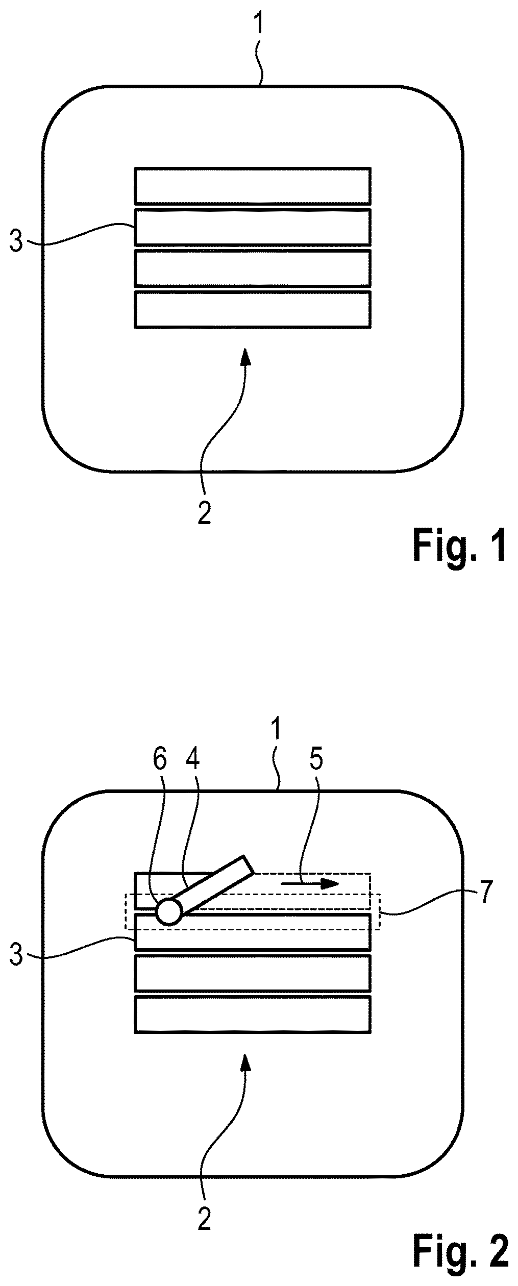
[0018]FIG. 1 illustrates a component 1, on which a schematic printed pattern 2 is arranged. The printed pattern 2 comprises individual partial structures in the form of printed strips 3 that are arranged close together. Free spaces are arranged between the printed strips 3 to illustrate that the printed strips 3 are not printed right up against one another during the printing but at small distances from one another. It is usually attempted to choose the viscosity of the paint such that the paint runs or flows a little at the margins of the printed strips, and as a result the free spaces are closed.

[0019]FIG. 2 illustrates an embodiment of the printing method according to the invention on the basis of the printed pattern 2 shown in FIG. 1. The individual printed strips 3 are printed by a printhead 4, which by way of example has a rectangular form here. The printhead 4 in this case is moved from left to right in a printing direction indicated by the arrow 5 and applies the strips 3 in...


PUM

PropertyMeasurementUnit
Timeaaaaaaaaaa
Structureaaaaaaaaaa
Viscosityaaaaaaaaaa

Abstract

A method for printing a surface (1) with a printed pattern (2) includes printing a first partial structure (3) of the printed pattern (2), printing a second partial structure (3) of the printed pattern (2) at a distance from the first printed structure (3) and treating at least one region (7) between the first printed structure (3) and the second printed structure (3), and the irradiating the region (7) between the first printed structure (3) and the second printed structure (3) with electromagnetic waves and / or soundwaves.

Description

CROSS REFERENCE TO RELATED APPLICATION[0001]This application claims priority under 35 USC 119 to German Patent Appl. No. 10 2019 102 247.9 filed on Jan. 30, 2019, the entire disclosure of which is incorporated herein by reference.BACKGROUNDField of the Invention[0002]The invention relates to a method for printing a surface with a printed pattern, in particular for printing onto a vehicle body. The method is carried out to include a smoothing of the regions between partial structures of the printed pattern during the printing operation. The invention also relates to an associated printing device.Related Art[0003]A known technology allows a pattern, such as rally stripes to be printed onto a vehicle body in a manner similar to a conventional printer. For example, DE 10 2014 221 103 A1 discloses a method for printing automobile bodies along multiple lines. Printing operations of this type use a printhead that prints two-dimensional patterns to be printed in individual strips of paint o...

Claims


Application Information

Patent Timeline
IPC IPC(8): B41J11/00
CPCB41J11/002B41M5/00B41M1/28B41M7/00B41M7/0081B41J2/435B41J3/4073B05D1/40B05D3/06B05D3/065B41M7/009B41M3/00B41J11/00214B41J11/00216B05C9/12B05C5/0208B05D3/0263B41J11/0015
Inventor KOMOLZEW, ROMAN
Owner DR ING H C F PORSCHE AG
Why Eureka
Try Eureka