Imaging system, developing system, and imaging method

Inactive Publication Date: 2020-07-30
RICOH KK
View PDF14 Cites 18 Cited by
  • Summary
  • Abstract
  • Description
  • Claims
  • Application Information

AI Technical Summary

Problems solved by technology

Thus, even if a user views a thumbnail image displayed on a display unit of the external de

Method used


Image

  • Imaging system, developing system, and imaging method
  • Imaging system, developing system, and imaging method
  • Imaging system, developing system, and imaging method

Examples


first embodiment

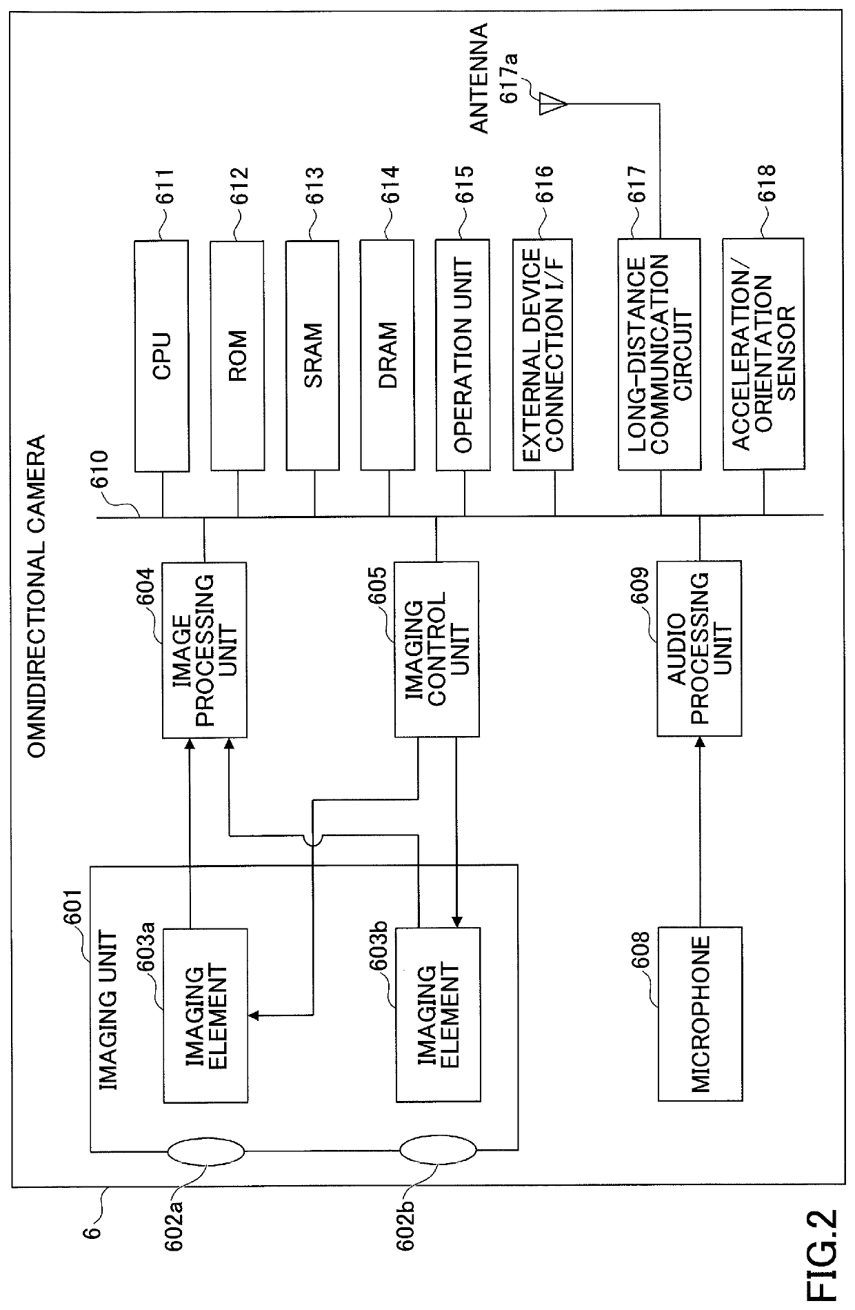
[0065]Next, referring to FIG. 6, a functional configuration of the omnidirectional camera 6 will be described. FIG. 6 is block diagram illustrating an example of the functional configuration of the omnidirectional camera 6. Note that FIG. 6 illustrates the concept of functional blocks, and the functional blocks are not required to be physically configured as illustrated in FIG. 6. All or some of the functional blocks may be functionally or physically separated or combined in any unit. Further, the omnidirectional camera 6 may include functions other than the functions illustrated in FIG. 6.

[0066]As illustrated in FIG. 6, the omnidirectional camera 6 includes an imaging unit 651, an image processing unit 652, an arranged image generating unit 660, a thumbnail image generating unit 670, an output data generating unit 680, and an output unit 690.

[0067]The imaging unit 651 is implemented by, for example, the imaging unit 601 and the imaging control unit 605. The imaging unit 651 include...

second embodiment

[0121]Next, a developing system according to a second embodiment will be described. A description of the same elements as those of the above-described embodiment will be omitted.

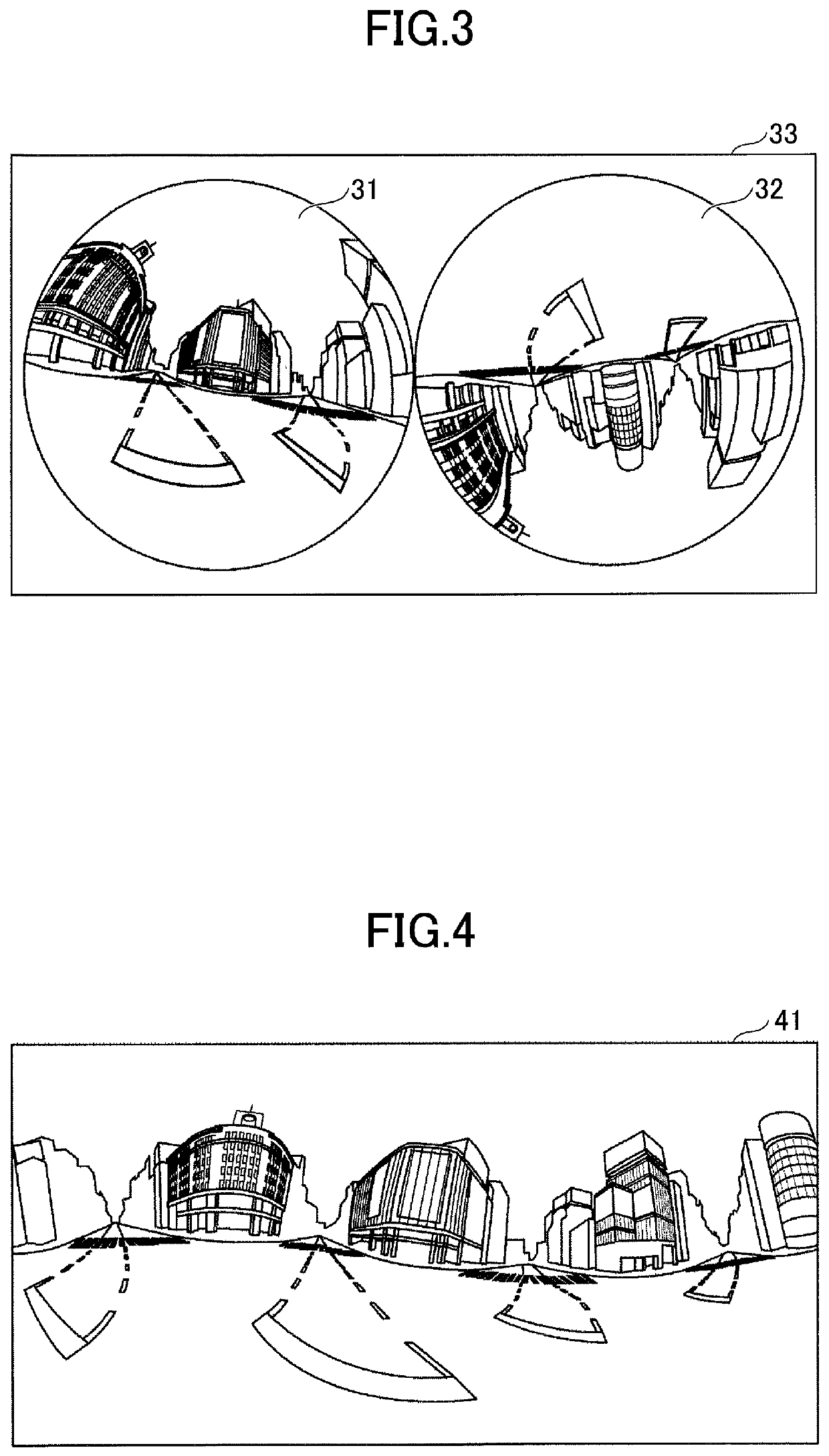
[0122]Due to variations in a manufacturing process of the fisheye lenses 602a and 602b or the imaging elements 603a and 603b, spectral sensitivity characteristics may differ between two fisheye images captured by the imaging unit 651. If two fisheye images that have different hues due to different spectral sensitivity characteristics are stitched together, a generated spherical image may become unnatural.

[0123]As a measure of hue, hue may be sometimes represented as each color gain of an image. As a specific example, there are assumed to be one fisheye image with a red (R) gain of 2.0 and a blue (B) gain of 2.0 and the other fisheye image with a red (R) gain of 1.95 and a blue (B) gain of 2.05.

[0124]In this case, as compared to the one fisheye image, the other fisheye image appears as reddish. In the case of...


PUM


Abstract

An imaging system includes an imaging unit configured to capture a plurality of fisheye images; an arranged image generating unit configured to generate an arranged image in which the plurality of fisheye images are arranged; a thumbnail image generating unit configured to generate a thumbnail image that includes at least a part of a spherical image, the spherical image being generated based on the plurality of fisheye images; and an output unit configured to output output data that includes the arranged image and the thumbnail image.

Description

CROSS-REFERENCE TO RELATED APPLICATIONS[0001]The present application claims priority under 35 U.S.C. § 119 to Japanese Patent Application No. 2019-014876, filed on Jan. 30, 2019, the entire contents of which are incorporated herein by reference.BACKGROUND OF THE INVENTION1. Field of the Invention[0002]The disclosures herein relate to an imaging system, a developing system, and an imaging method.2. Description of the Related Art[0003]Conventionally, an omnidirectional imaging system that uses multiple wide-angle lenses such as fisheye lenses or super wide-angle lenses to capture an omnidirectional image (hereinafter referred to as a “spherical image”) at one time is known (see Patent Document 1, for example).[0004]In such an omnidirectional imaging system, in order to properly perform a RAW development process for images of objects captured in all directions, it is preferable to output the captured raw image data to an external device such as a personal computer (PC) or a tablet, and...

Claims


Application Information

Patent Timeline
IPC IPC(8): H04N5/232H04N9/64
CPCH04N5/23293H04N5/23238H04N5/23229H04N9/646H04N23/80H04N23/698H04N23/63
Inventor HOHJOH, DAISUKE
Owner RICOH KK
Why Eureka
Try Eureka