
Balloon expandable frame for transcatheter implantation of a cardiac valve prosthesis

Active Publication Date: 2020-08-06
MEDTRONIC INC
View PDF0 Cites 6 Cited by
  • Summary
  • Abstract
  • Description
  • Claims
  • Application Information

AI Technical Summary

Benefits of technology

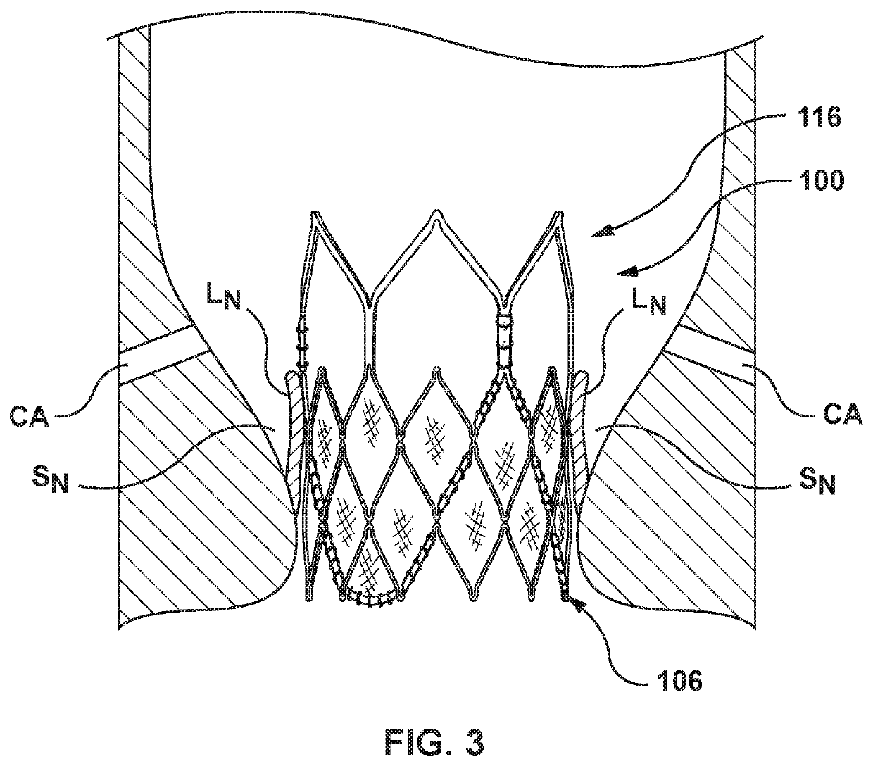
The patent relates to a valve prosthesis that can be used to treat heart valve disease. The prosthesis includes a stent and a prosthetic valve that is secured to the stent. The stent is balloon expandable and has a crimped configuration for delivery and an expanded configuration for deployment within the native heart valve. The stent is designed to be inserted into the vein system and has a unique design to improve its flexibility and positioning within the heart valve. The prosthetic valve is secured to the stent and can regulate blood flow through the heart valve. The stent is made of a plurality of struts and crowns that create a valve to prevent blood flow in one direction. The stent has three rows of struts and crowns in the inflow portion and a single row of struts and crowns in the outflow portion. This design improves the function and flexibility of the valve prosthesis and ensures proper placement within the heart valve. The technical effects of this patent are an improved valve prosthesis with a stent that is easier to insert, better positioned, and can better regulate blood flow through the heart valve.

Problems solved by technology

Problems that may develop with valves include stenosis in which a valve does not open properly, and / or insufficiency or regurgitation in which a valve does not close properly.
Stenosis and insufficiency may occur concomitantly in the same valve.
The effects of valvular dysfunction vary, with regurgitation or backflow typically having relatively severe physiological consequences to the patient.

Method used


Image

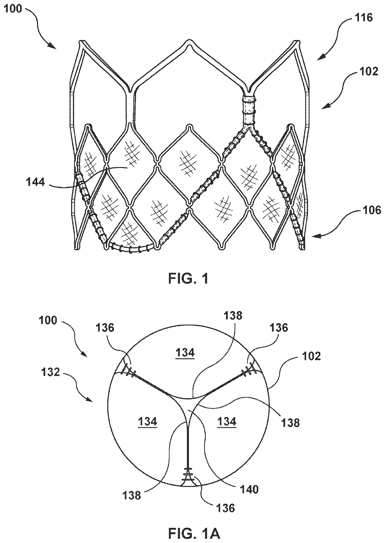
  • Balloon expandable frame for transcatheter implantation of a cardiac valve prosthesis
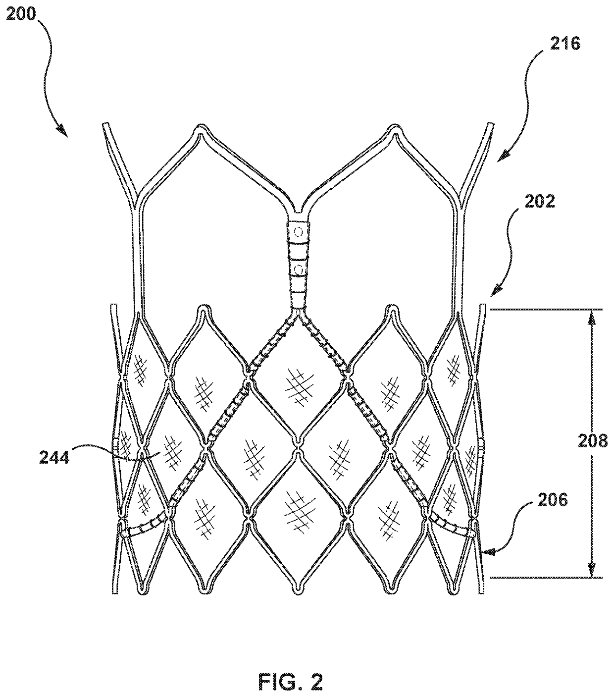
  • Balloon expandable frame for transcatheter implantation of a cardiac valve prosthesis
  • Balloon expandable frame for transcatheter implantation of a cardiac valve prosthesis

Examples


first embodiment

[0120] hereof, a transcatheter valve prosthesis includes a stent having a crimped configuration for delivery within a vasculature and an expanded configuration for deployment within a native heart valve. The stent is balloon expandable and includes an inflow portion, an outflow portion, and a transition portion extending between the inflow portion and the outflow portion. The inflow portion is formed proximate to an inflow end of the stent. The inflow portion includes a plurality of crowns and a plurality of struts with each crown being formed between a pair of opposing struts, a plurality of side openings being defined by the plurality of crowns and the plurality of struts. Endmost inflow side openings and endmost inflow crowns are formed at the inflow end of the stent. The inflow end of the stent has a total of twelve endmost inflow crowns. The outflow portion is formed proximate to an outflow end of the stent. The outflow portion includes a plurality of crowns and a plurality of ...

second embodiment

[0136] hereof, a transcatheter valve prosthesis includes a stent having a crimped configuration for delivery within a vasculature and an expanded configuration for deployment within a native heart valve. The stent is balloon expandable. The stent includes an inflow portion and an outflow portion. The inflow portion is formed proximate to an inflow end of the stent. The inflow portion includes a plurality of crowns and a plurality of struts with each crown being formed between a pair of opposing struts, a plurality of side openings being defined by the plurality of crowns and the plurality of struts. Endmost inflow side openings and endmost inflow crowns are formed at the inflow end of the stent and the inflow end of the stent has a total of twelve endmost inflow crowns. The outflow portion is formed proximate to an outflow end of the stent. The outflow end of the stent has a total of three commissure posts, each commissure post longitudinally extending from a crown of the inflow end...

third embodiment

[0145] hereof, a transcatheter valve prosthesis includes a stent having a crimped configuration for delivery within a vasculature and an expanded configuration for deployment within a native heart valve. The stent is balloon expandable. The stent includes a plurality of axial frame members, an inflow portion, and an outflow portion. The inflow portion includes at least three rows of struts and crowns formed between adjacent pairs of said struts. The at least three rows of the inflow portion are formed between an inflow end of the axial frame members and an inflow end of the stent. The outflow portion includes a single row of struts and crowns formed between adjacent pair of said struts. The outflow portion is coupled to an outflow end of the axial frame members. Exactly two struts of the plurality of struts of the outflow portion are disposed between adjacent axial frame members.

[0146]In an aspect of the third embodiment, and in combination with any other aspects herein, the plurali...


PUM


Abstract

A transcatheter valve prosthesis includes a balloon expandable stent and a prosthetic valve. An inflow portion of the stent includes a plurality of crowns and a plurality of struts with each crown being formed between a pair of opposing struts. Endmost inflow side openings and endmost inflow crowns are formed at the inflow end of the stent and the inflow end of the stent has a total of twelve endmost inflow crowns. An outflow portion of the stent includes a plurality of crowns and a plurality of struts with each crown being formed between a pair of opposing struts. Endmost outflow crowns are formed at the outflow end of the stent and the outflow end of the stent has a total of six endmost outflow crowns. The prosthetic valve is disposed within and secured to the stent.

Description

CROSS-REFERENCE TO RELATED APPLICATIONS[0001]This application claims the benefit of U.S. Provisional Patent Application Ser. No. 62 / 801,041, filed Feb. 4, 2019, which is hereby incorporated by reference in its entirety for all purposes. This application also claims the benefit of U.S. Provisional Patent Application Ser. No. 62 / 880,879, filed Jul. 31, 2019, which is hereby incorporated by reference in its entirety for all purposes.FIELD OF THE INVENTION[0002]The present invention relates to transcatheter valve prostheses that are radially expandable by a balloon.BACKGROUND OF THE INVENTION[0003]A human heart includes four heart valves that determine the pathway of blood flow through the heart: the mitral valve, the tricuspid valve, the aortic valve, and the pulmonary valve. The mitral and tricuspid valves are atrioventricular valves, which are between the atria and the ventricles, while the aortic and pulmonary valves are semilunar valves, which are in the arteries leaving the heart....

Claims


Application Information

Patent Timeline
IPC IPC(8): A61F2/24
CPCA61F2/2433A61F2250/001A61F2/2418A61F2/9522A61F2230/0054A61F2250/0036A61F2230/0069A61F2230/0006
Inventor PETERSON, JUSTINGOSHGARIAN, JUSTINKARI, STUARTTIEN, TRACEYKRIVORUCHKO, MICHAELNEUBERGER, YASJAVANI, SHAHNAZBALDWIN, MATTHEWRINNE, FINN
Owner MEDTRONIC INC
Learn More