
Vehicle park assist systems

a technology for assist systems and vehicles, applied in the field of vehicles, can solve problems such as the finite amount of storage space of certain vehicles

Inactive Publication Date: 2020-08-06
CARIT AUTOMOTIVE
View PDF9 Cites 13 Cited by
  • Summary
  • Abstract
  • Description
  • Claims
  • Application Information

AI Technical Summary

Benefits of technology

The patent describes a system that helps create a safe path for a vehicle and trailer in a computer-generated environment. If the path is too short and crosses a prohibited area, the system adds an overlay grid to the representation of the environment. The grid points are connected to positions in the environment. The system also modifies the shortest path to match the grid points within the acceptable area, creating a custom path. The system can be used in autonomous vehicles. The technical benefit of this system is to help ensure safe travel through computer-generated environments.

Problems solved by technology

In some cases, certain vehicles have a finite amount of storage space.

Method used


Image

  • Vehicle park assist systems
  • Vehicle park assist systems
  • Vehicle park assist systems

Examples


example 1

Practical Example 1

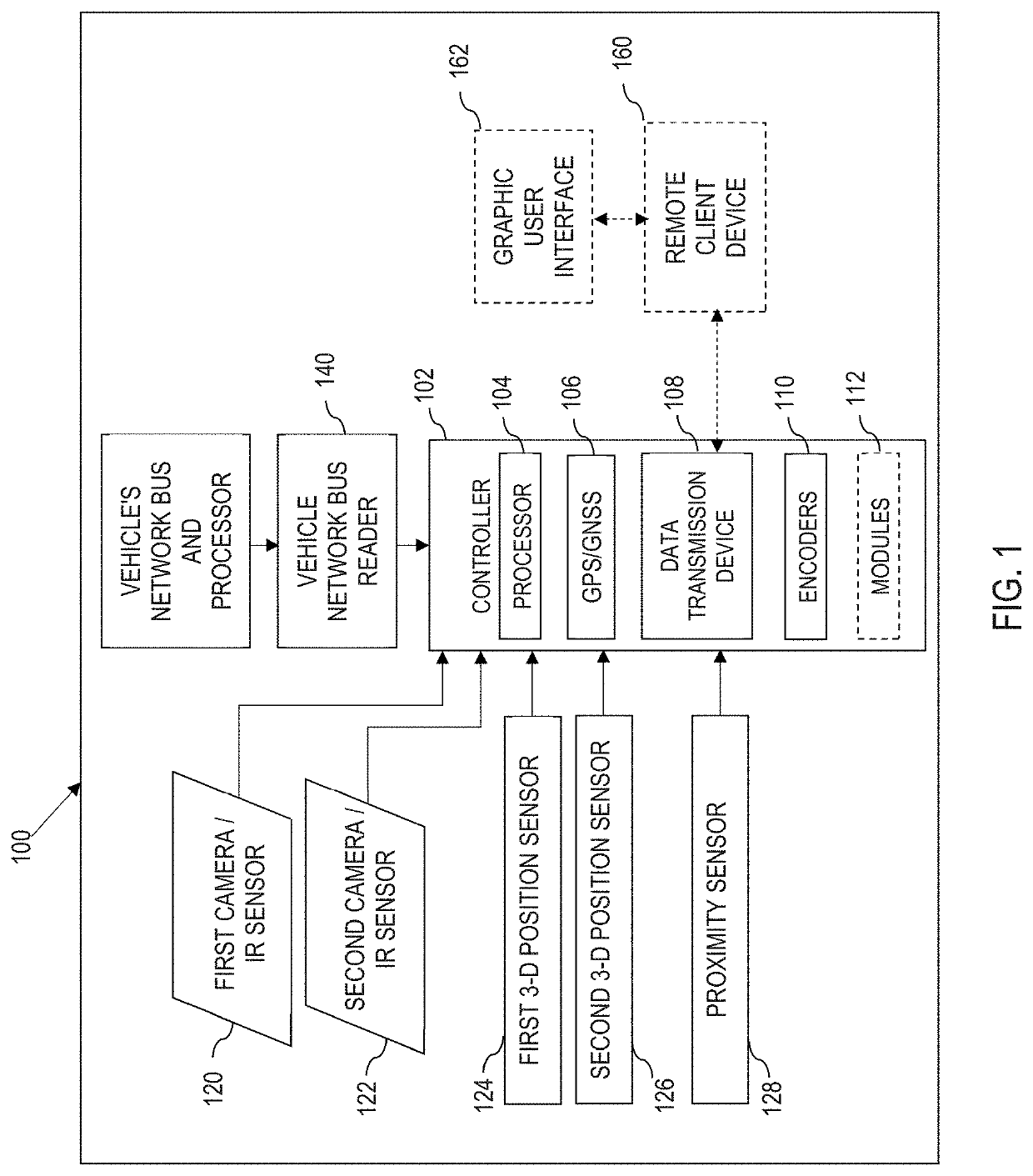
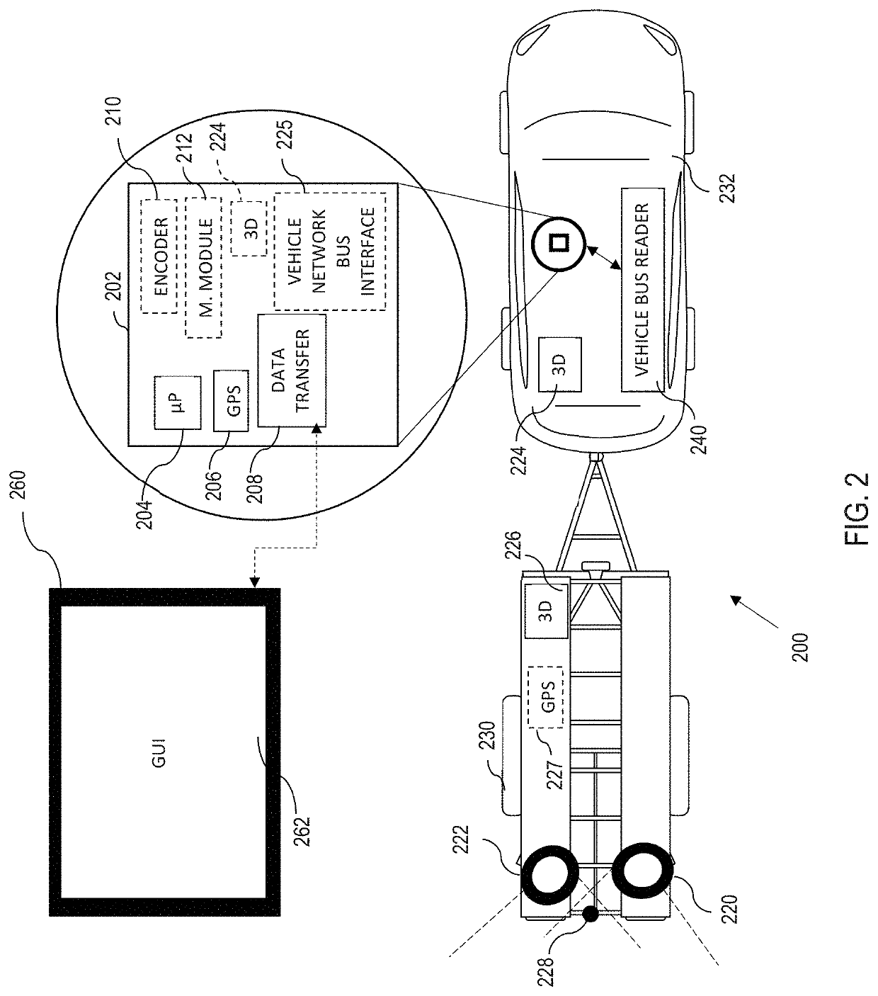
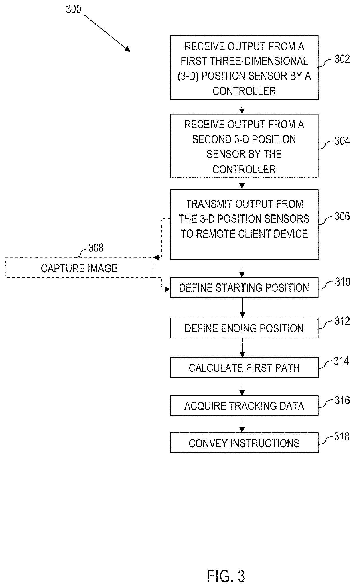
[0099]FIGS. 4A-D illustrate example embodiments of defining 310 the starting position, defining 312 the ending position, and calculating 314 the custom path. The numbered components of FIG. 4 (and its sub figures) match the numbered components of FIG. 1, including the definitions and embodiments thereof, except that the numbers in FIG. 4 are 300 higher. The various systems, processes, hardware, and embodiments disclosed in FIGS. 1-3 and can be combined in any combination of components described with reference thereto. In this regard, not every disclosed component need be incorporated.

[0100]In FIG. 4A, a remote client device 460 with a graphical user interface (GUI) GUI 462 is illustrated. A trailer 430 and a vehicle 432 are shown as graphical representations along with a corresponding first 3-D position sensor 424 and a second 3-D position sensor 426. The broken lines are example representations of position data (e.g., angular data), which are not required. In var...

example 2

Practical Example 2

[0108]Now referring to FIG. 5A, which is the first figure in a series that illustrates how various implementations of the present disclosure (e.g., the process 300) create and use a custom path. The numbered components of FIG. 5 (and its sub figures) match the numbered components of FIGS. 4A-D, including the definitions and embodiments thereof, except that the numbers in FIG. 5 are 100 higher. The various systems, processes, hardware, and embodiments disclosed in FIGS. 1-4D and can be combined in any combination of components described with reference thereto. In this regard, not every disclosed component need be incorporated.

[0109]Now referring to FIG. 5A, an overhead view of a vehicle 532 and a trailer 530 are shown on a GUI 562 within a remote client device 560. In this regard, the vehicle 532 and the trailer 530 can be graphical representations or a live representation thereof (e.g., via Google Earth), which is aided by the GPS and other vehicle metrics (e.g., ...


PUM


Abstract

A vehicle-trailer system is disclosed. The system utilizes a controller that has a processor, a global positioning system that provides a geographic position to the processor, a data transmission device that sends and receives data through the controller and a camera signal encoder. The system also includes various three-dimensional (3-D) position sensors, which measure changes in spatial position with reference to location on three axes (e.g., 3-D compass comprising a magnetometer, a gyroscope, and an accelerometer). Moreover, the system comprises a vehicle network bus reader that communicates vehicle information from the vehicle network bus to the controller (e.g., controller area network (CAN) bus, or a local interconnect network (LIN) bus) wherein the controller is capable of communicably coupling to a remote client device, the remote client device configured to convey steering instructions.

Description

CROSS REFERENCE TO RELATED APPLICATIONS[0001]This application is a bypass continuation of International Application No. PCT / IB2019 / 000078, filed Feb. 1, 2019, entitled VEHICLE PARK ASSIST SYSTEMS, the disclosure of which is hereby incorporated herein by reference.BACKGROUND[0002]Various aspects of the present disclosure relate generally to vehicle-assisted systems, and specifically guidance of vehicle-assisted trailers.[0003]Vehicles such as cars, trucks, and vans are used to transport people and miscellaneous items across varying distances. In some cases, certain vehicles have a finite amount of storage space. One potential solution to supplement that finite storage space is through utilization of trailers. Trailers come in many shapes and sizes that can accommodate various needs of the user such as horse trailers, bicycle trailers, motorcycle trailers, boat trailers, and semi-truck trailers.BRIEF SUMMARY[0004]According to aspects of the present disclosure, a trailer park-assist sy...

Claims


Application Information

Patent Timeline
Patent Type & Authority Applications(United States)
IPC IPC(8): B62D15/02B62D13/06B60W10/20B60W50/04B60R11/04H04L12/40
CPCB60R11/04H04L2012/40273B60W10/20B62D13/06H04L12/40013B60W50/045B60W2300/14B62D15/028B60W2556/60B60W2050/046H04L2012/40215B60R2011/004B62D15/0275B60Y2300/28B60W2050/0064B62D15/0285H04N7/183G06V20/58B60W2556/50
Inventor GRODDE, GUENTER
Owner CARIT AUTOMOTIVE
Learn More