

Composite-type heat type
a heat pipe and composite technology, applied in the direction of indirect heat exchangers, lighting and heating apparatus, etc., can solve the problems of affecting the working state and the gaseous working fluid, reducing the speed of diffusing or returning the working fluid, and still having some drawbacks of the conventional heat pipe structure, etc., to achieve the effect of increasing the flow space of the gaseous working liquid and increasing the speed of returning the liquid working fluid
- Summary
- Abstract
- Description
- Claims
- Application Information
AI Technical Summary
Benefits of technology
Problems solved by technology
Method used
Image

Examples
second embodiment
[0040]In the second embodiment, two trenches have the larger widths. It is noted that the number of the wider trenches is not restricted. That is, the second capillary structure may comprise more than two wider trenches or at least one wider trench.
first embodiment
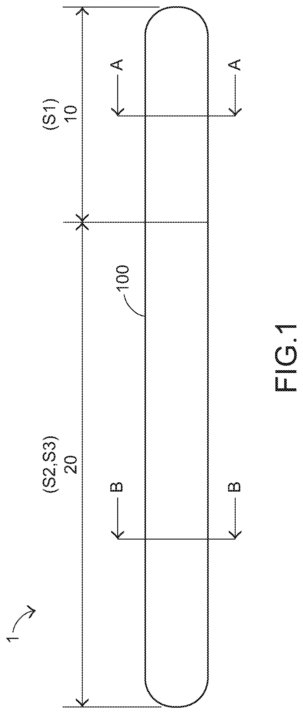
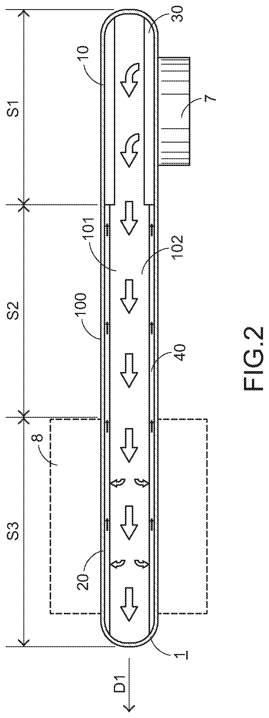
[0041]Alternatively, the relationships between the first section (and the second section) and the condensation section, the transfer section and the heating section are not restricted. In the first embodiment, the portion of the first section 10 corresponding to the smooth surface 31 is used as the heating section S1, and the portion of the second section 20 corresponding to the trenches 41 is used as the condensation section S3 and the transfer section S2. However, the structure of the transfer section is not restricted.
[0042]A third embodiment of the present invention will be described as follows. FIG. 7 is a schematic cross-sectional side view illustrating the applications of a composite-type heat pipe according to a third embodiment of the present invention. Component parts and elements corresponding to those of the first embodiment are designated by similar numeral references. In comparison with the first embodiment, the second section 20a with the second capillary structure 40...
PUM
 Abstract
Description
Claims
Application Information