Contact pin for pressing into a printed circuit board and contact arrangement

a technology of printed circuit board and contact arrangement, which is applied in the direction of connecting, contact material of connection, electrical or electronic circuit, etc., can solve the problems of failure of the printed circuit board, inability to apply sufficient spring force to retain the contact pin in the through-hole during service life, and inability to apply sufficient spring force in the crosspiece area

Active Publication Date: 2020-08-06
ROBERT BOSCH GMBH
View PDF0 Cites 0 Cited by
  • Summary
  • Abstract
  • Description
  • Claims
  • Application Information

AI Technical Summary

Benefits of technology

[0012]This need may be met by the subject of the present invention according to the independent claims. Advantageous embodiments of the present invention are described in the dependent claims.
[0013]The terms “comprising” and “having” are synonymously used throughout the application, unless otherwise expressly stated.

Problems solved by technology

This may be disadvantageous if multiple printed circuit boards are to be stacked on top of each other, for example in an electrical device, e.g. a control unit, as the projection prevents the printed circuit boards from being arranged closer together.
This may have undesirable effects on adjacent electrical or electronic circuits.
If, on the other hand, the resilient region will exclusively be formed by the crosspiece area, which crosspiece area deforms whereas the wing areas which are adjacent to the crosspiece area on both sides do not deform, there will be the risk, on the one hand, for the crosspiece area not to be able to apply sufficient spring force for retaining the contact pin in the through-hole during service life.
Furthermore, there is a risk that the ear areas formed adjacent to each of the wing areas, due to their stiffness, could damage the inner walls of the through-hole during press-fitting or during subsequent vibration loads, which could lead to failure of the printed circuit board.
This undesirably reduces possible packing density of a printed circuit board in the lateral direction.
In addition, the current-carrying capacity may be limited, as only a small portion of the outer contour of the crimp zone is in mechanical and therefore also electrical contact with the through-hole, and in some cases there is even nothing but punctual contact.

Method used


Image

  • Contact pin for pressing into a printed circuit board and contact arrangement
  • Contact pin for pressing into a printed circuit board and contact arrangement
  • Contact pin for pressing into a printed circuit board and contact arrangement

Examples


Embodiment Construction

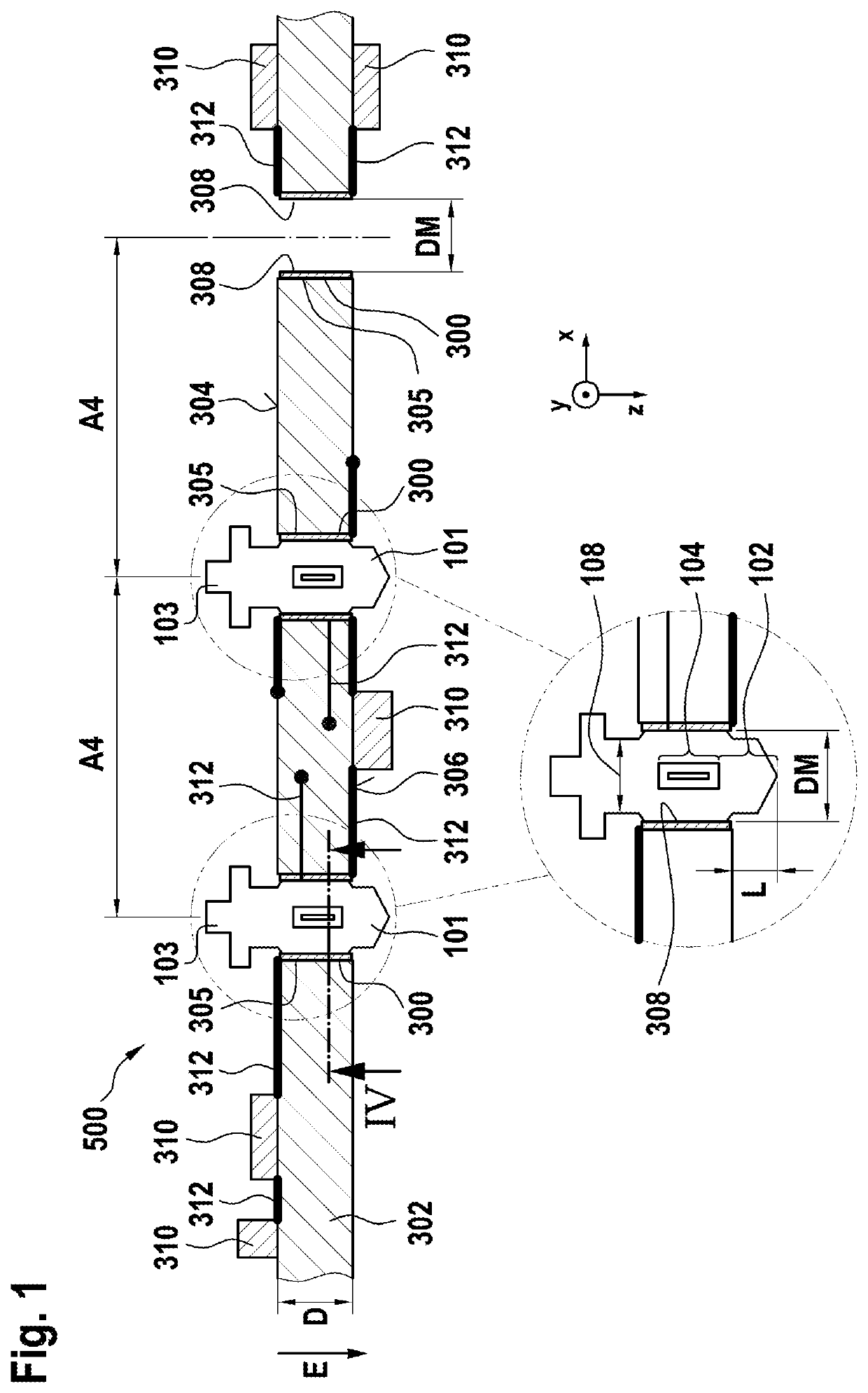
[0060]FIG. 1 shows an electrical contact arrangement 500. The contact arrangement 500 comprises:

a printed circuit board 302 having a through-hole 300 extending along a Z-direction,

an electrical contact pin 100, which is crimped in the through-hole 300 or press-fitted into the through-hole 300, respectively.

[0061]For example, the printed circuit board 302 may be a rigid printed circuit board 302. It may be made of FR4 material or any superior material (FR-5, FR6, etc.). The printed circuit board 302 may for example be a single layer printed circuit board. However, it may also comprise two layers or even more than two layers. The printed circuit board 302 has a first side 304, which may be referred to as the top side or front side (top side in the figure). The printed circuit board 302 also has a second side 306, which is opposite to the first side 304 and may be referred to as the bottom side or back side. The printed circuit board 302 may also comprise at least one conductive track ...


PUM


Abstract

An electrically conductive contact pin for press-fitting into a PCB in a Z-direction. The contact pin includes a press-fit zone with a central crosspiece area, and two wing areas adjacent to the crosspiece area, each crosspiece area having two ear areas. The crosspiece area is confined by a crosspiece rectangle and the ear regions are confined by ear rectangles. Corner points of the ear rectangles facing a center of the cross-sectional area coincide with corner points of the crosspiece rectangle. The crosspiece rectangle has a crosspiece width in an X direction of 9-29% of a starting thickness of the contact pin and a crosspiece thickness in a Y direction of 35-55% of the starting thickness. The ear rectangles have an ear width in the X-direction of 40-60% of the starting thickness and an ear thickness in the Y-direction of 15-35% of the starting thickness.

Description

FIELD OF THE INVENTION[0001]The invention relates to a contact pin for press-fitting into a printed circuit board and a contact arrangement comprising a contact pin and a printed circuit board.PRIOR ART[0002]Printed circuit boards may be used for a multitude of applications, for example creating circuits comprising a plurality of electrical or electronic components, wherein connections of the components or cables or wires, respectively, may electrically be connected to conductive tracks of the printed circuit board. One approach to achieve this is the so-called press-fit technique. A contact pin may be press-fitted into a channel-like through-hole or recess in the circuit board, wherein the through-hole passes through two opposite sides of the circuit board. The contact pin has a larger diameter than the through-hole or recess, at least in some sections of the press-fit zone. When being press-fitted, the contact pin is crimped at least in the press-fit zone. To allow crimping, the c...

Claims


Application Information

Patent Timeline
Patent Type & Authority Applications(United States)
IPC IPC(8): H01R12/58H01R4/58
CPCH01R12/585H01R4/58
Inventor EICHER, HERMANNHABIGER, RALPHOTTO, ANDREASHALM, CYNTHIA
Owner ROBERT BOSCH GMBH
Why Eureka
Try Eureka