High pressure tank residual pressure determination system, high pressure tank residual pressure determination method, and fuel cell vehicle

Active Publication Date: 2020-08-13
HONDA MOTOR CO LTD
View PDF0 Cites 0 Cited by
  • Summary
  • Abstract
  • Description
  • Claims
  • Application Information

AI Technical Summary

Benefits of technology

The present invention provides a system and method for determining the residual pressure of a high pressure tank used in fuel cell vehicles. The system uses a usage limit threshold value to stop further release of gas from the tank, ensuring that the tank internal pressure does not decrease below the required minimum residual pressure line. This prevents the gas inside the tank from falling below the required minimum pressure limit, even if the tank temperature changes. The system also calculates the usage limit threshold value based on the tank internal pressure and temperature to ensure efficient use of the gas stored in the tank. Overall, the invention prevents the tank internal pressure from falling below the required minimum pressure limit, allowing for effective use of the gas stored in the tank.

Problems solved by technology

At this time, when the tank internal pressure becomes lower than the pressure of the gas that has entered into the covered portion, there is a concern that the liner and the reinforced layer may peel off or separate from one another, and the liner may undergo buckling or the like and protrude toward the interior thereof.

Method used


Image

  • High pressure tank residual pressure determination system, high pressure tank residual pressure determination method, and fuel cell vehicle
  • High pressure tank residual pressure determination system, high pressure tank residual pressure determination method, and fuel cell vehicle
  • High pressure tank residual pressure determination system, high pressure tank residual pressure determination method, and fuel cell vehicle

Examples


Embodiment Construction

[0026]Preferred embodiments of a high pressure tank residual pressure determination system, a high pressure tank residual pressure determination method, and a fuel cell vehicle according to the present invention will be presented and described in detail below with reference to the accompanying drawings. In the drawings discussed below, structural elements exhibiting the same or similar functions and effects are denoted by the same reference numerals, and repeated description of such components may be omitted.

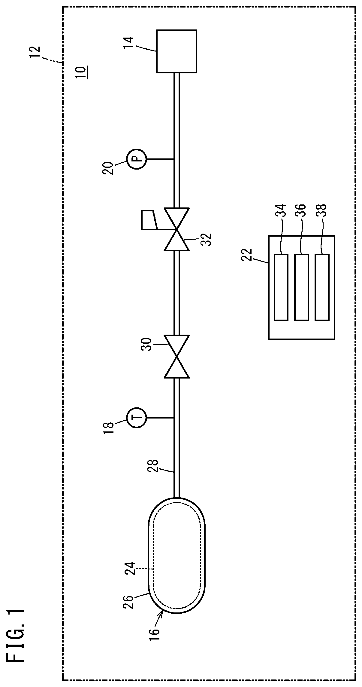
[0027]As shown in FIG. 1, the high pressure tank residual pressure determination system (hereinafter, referred to simply as a residual pressure determination system) 10 is capable of being suitably used as a system equipped with a high pressure tank 16 that is mounted on a mounting body defined by a fuel cell vehicle 12, and in which hydrogen gas that is supplied to a fuel cell 14 is stored. Thus, according to the present embodiment, although a description will be given concerni...


PUM


Abstract

A computation unit of a residual pressure determination system obtains a corresponding usage limit threshold value corresponding to a measured temperature value of a tank temperature, from a usage limit threshold value line calculated using at least one of a required minimum residual pressure line and an isopycnic line. When having determined that a measured internal pressure value has decreased to the corresponding usage limit threshold value, a determination unit stops release of hydrogen gas from a high pressure tank. A tank internal pressure indicated by the usage limit threshold value line within an allowable temperature range becomes greater than or equal to the tank internal pressure indicated by the isopycnic line or that indicated by a tangent line, and at least a portion of the tank internal pressure indicated by the usage limit threshold value line within the allowable temperature range becomes lower as the tank temperature becomes lower.

Description

CROSS-REFERENCE TO RELATED APPLICATION[0001]This application is based upon and claims the benefit of priority from Japanese Patent Application No. 2019-022470 filed on Feb. 12, 2019, the contents of which are incorporated herein by reference.BACKGROUND OF THE INVENTIONField of the Invention[0002]The present invention relates to a residual pressure determination system for a high pressure tank having a resin liner capable of storing a gas therein and a reinforced layer that covers an outer surface of the liner, a residual pressure determination method for the high pressure tank, and a fuel cell vehicle.Description of the Related Art[0003]For example, as disclosed in Japanese Laid-Open Patent Publication No. 2003-172654, a pressure (tank internal pressure) of a gas stored in a high pressure tank changes in accordance with a temperature (tank temperature) of a gas inside the high pressure tank, even if a density of the gas inside the high pressure tank is kept the same.[0004]Incidental...

Claims


Application Information

Patent Timeline
IPC IPC(8): H01M8/0438G05D16/20G01L19/00H01M8/0432H01M8/04082H01M8/04746
CPCG01L19/0092H01M2250/20G05D16/2013H01M8/04753H01M8/04201H01M8/04425H01M8/04373F17C13/025F17C13/026F17C1/16F17C7/00F17C2203/011F17C2221/012F17C2225/03F17C2227/048F17C2250/043F17C2250/0439F17C2250/0631F17C2250/0626F17C2250/072F17C2270/0168Y02E60/50Y02E60/32Y02T90/40F17C2201/0109F17C2201/056F17C2201/058F17C2205/0326F17C2270/0184F17C2203/0604F17C2203/0658F17C2223/0123F17C2223/036F17C2203/0663F17C2250/032F17C2260/026
Inventor KAWASE, SATORUKADOWAKI, KAZUYUKI
Owner HONDA MOTOR CO LTD
Why Eureka
Try Eureka