Static pressure seal-equipped motor

a technology of sealing and motors, applied in the direction of mechanical equipment, engine components, bearing units, etc., can solve the problems of increasing the vibration of the shaft, increasing the axial direction length of the hollow motor shaft, etc., and achieve the effect of reducing the size of the motor

Active Publication Date: 2018-04-26
HARMONIC DRIVE SYST IND CO LTD
View PDF1 Cites 0 Cited by
  • Summary
  • Abstract
  • Description
  • Claims
  • Application Information

AI Technical Summary

Benefits of technology

[0008]By using the static pressure seal, it is possible for the seal part between the rotating parts and the fixed parts of the motor to be made compact, which is advantageous for flattening the motor. However, in the rotary type motor disclosed in Patent Document 2, a circumferential groove for the static pressure seal and an air supply path for supplying sealing gas to the circumferential groove are formed in the constituent components of the motor case. Also, sealed spaces for making the internal pressure higher than the internal pressure of the motor chamber are formed on each of the outer sides of the motor bearings on both sides by the sealing gas that leaks out from the static pressure seal. Thus, the static pressure seal and the air supply path are formed on the motor case and the sealed spaces are provided at both sides of the motor bearing, wherefore the structure increases in complexity and size, which is undesirable for reducing the size of the motor.

Problems solved by technology

Since a drive mechanism provided with such a seal part requires a prescribed shaft length to ensure sealing performance, the axial-direction length of the hollow motor shaft inevitably increases.
An increase in the distance from the bearing position of the hollow motor shaft to the seal position, results in an increase in shaft vibration, etc.

Method used


Image

  • Static pressure seal-equipped motor
  • Static pressure seal-equipped motor
  • Static pressure seal-equipped motor

Examples


Embodiment Construction

[0041]An embodiment of the static pressure seal-equipped motor to which the present invention is applied is described below with reference to the accompanying drawings. The embodiment described hereafter is an example of when the present invention is used as the drive mechanism used for cleaning of wafers, etc. However, the static pressure seal-equipped motor of the present invention can be used for various types of drive mechanisms that require sealing between the motor installed atmosphere, and the peripheral atmosphere such as of a cleanroom, etc. in which that is enclosed.

(Overall Structure)

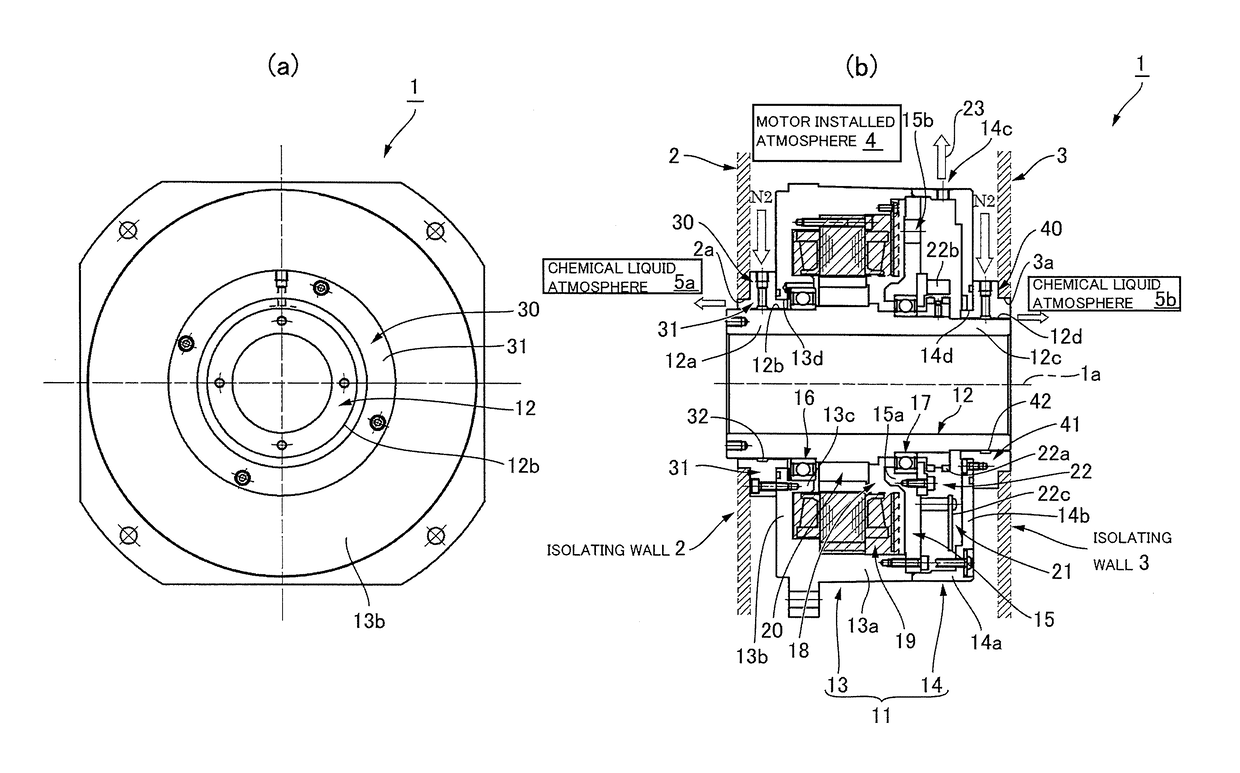
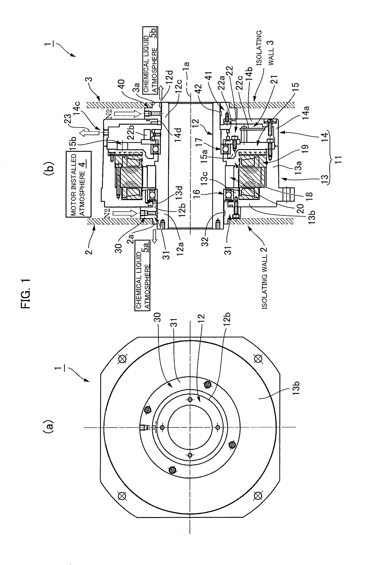
[0042]FIG. 1(a) is a front view of the static pressure seal-equipped motor of the present embodiment, and FIG. 1(b) is a cross sectional view thereof. A static pressure seal-equipped motor 1 is disposed in a state extended between a pair of isolating walls 2, 3 which are constituent components of a container of a wafer cleaning device, the space between the isolating walls 2, 3 is a motor ins...


PUM


Abstract

A static pressure seal-equipped motor (1) in which front and rear gaps are sealed by first and second static pressure seal portions (30, 40) disposed at first and second axial end portions (12a, 12c) of a motor rotating shaft (12) protruding toward front and rear. Sealing gas supplied to sealing gaps (32, 42) of the first and second static pressure seal portions (30, 40) is caused to diverge and flow to chemical liquid atmospheres (5a, 5b) and a motor chamber (18) or an encoder chamber (21) into the chemical liquid atmospheres (5a, 5b), and also prevent entry of chemical liquid-containing gas from the chemical liquid atmospheres (5a, 5b) into the motor chamber (18) or encoder chamber (21).

Description

TECHNICAL FIELD[0001]The present invention relates to a static pressure seal-equipped motor used, e.g., as a drive source, etc., for a wafer cleaning device, a chemical coating device, or a wafer conveying device, etc., used in a semiconductor manufacturing process.BACKGROUND ART[0002]The drive mechanism of the configuration disclosed in Patent Document 1 is known as a drive mechanism used for wafer cleaning, etc. In the drive mechanism disclosed therein, a rotary table is attached to the tip of a hollow motor shaft disposed vertically inside a container, the rotary table is caused to rotate, and cleaning liquid is sprayed on a wafer placed thereon from a supply nozzle disposed on the upper side. To ensure sealing on both the outer circumference side and the inner circumference side of the hollow shaft, a labyrinth seal is disposed on the outer circumference side and the inner circumference side of the hollow shaft.[0003]Since a drive mechanism provided with such a seal part require...

Claims


Application Information

Patent Timeline
Patent Type & Authority Applications(United States)
IPC IPC(8): F16C32/06H01L21/02F16C33/72H01L21/67
CPCH02K5/22H02K5/15F16C19/54F16C35/042F16C41/007F16C2380/26H02K5/10H02K5/1732H02K11/215H02K2205/09H01L21/304F16C33/72F16J15/447H01L21/67011H01L21/683
Inventor MARUYAMA, TOSHIKIFURUTA, KAZUMASA
Owner HARMONIC DRIVE SYST IND CO LTD
Why Eureka
Try Eureka