Outer stator for reciprocating motor and manufacturing method thereof

a technology of reciprocating motors and stators, which is applied in the direction of positive displacement liquid engines, piston pumps, magnetic circuit shapes/forms/construction, etc., can solve the problems of deformation of core blocks b>14/b>, collision between stators and movers, and deformation of reliability and efficiency of motors, so as to reduce the size of motors and reduce the area of core blocks. , the effect of preventing the deformation of an outer stator

Inactive Publication Date: 2008-01-29
LG ELECTRONICS INC
View PDF13 Cites 7 Cited by
  • Summary
  • Abstract
  • Description
  • Claims
  • Application Information

AI Technical Summary

Benefits of technology

[0019]Therefore, an object of the present invention is to provide a stator of a reciprocating motor capable of preventing deformation of an outer stator, which is generated due to a molding material, and of reducing a size of a motor by reducing an area of a core block while maintaining an area of a magnetic flux the same.

Problems solved by technology

As shown, the reciprocating motor has a problem in that the core block 14 is deformed by being pressed in a central direction by molding pressure generated during injection of a molding agent and by contraction generated in hardening of a molding agent.
For this reason, a distance (t) between the outer stator 11 and the inner stator 12 gets narrowed, thereby undesirably causing collision between the stator and the mover.
Therefore, reliability and efficiency of the motor are degraded.
Also, because the injection molding method is used in an over molding process in which a winding coil is coated with an insulation material, a molded object is contracted in cooling, causing a dimensional error, and ununiformity of a product is generated by a temperature of a mold, which increases a rate of defection.
Therefore, there are several problems such as complicated manufacturing processes and an increased manufacturing cost.
Therefore, a size of the motor should be undesirably enlarged as much as the widened width.

Method used


Image

  • Outer stator for reciprocating motor and manufacturing method thereof
  • Outer stator for reciprocating motor and manufacturing method thereof
  • Outer stator for reciprocating motor and manufacturing method thereof

Examples


Embodiment Construction

[0032]Reference will now be made in detail to the preferred embodiments of the present invention, examples of which are illustrated in the accompanying drawings.

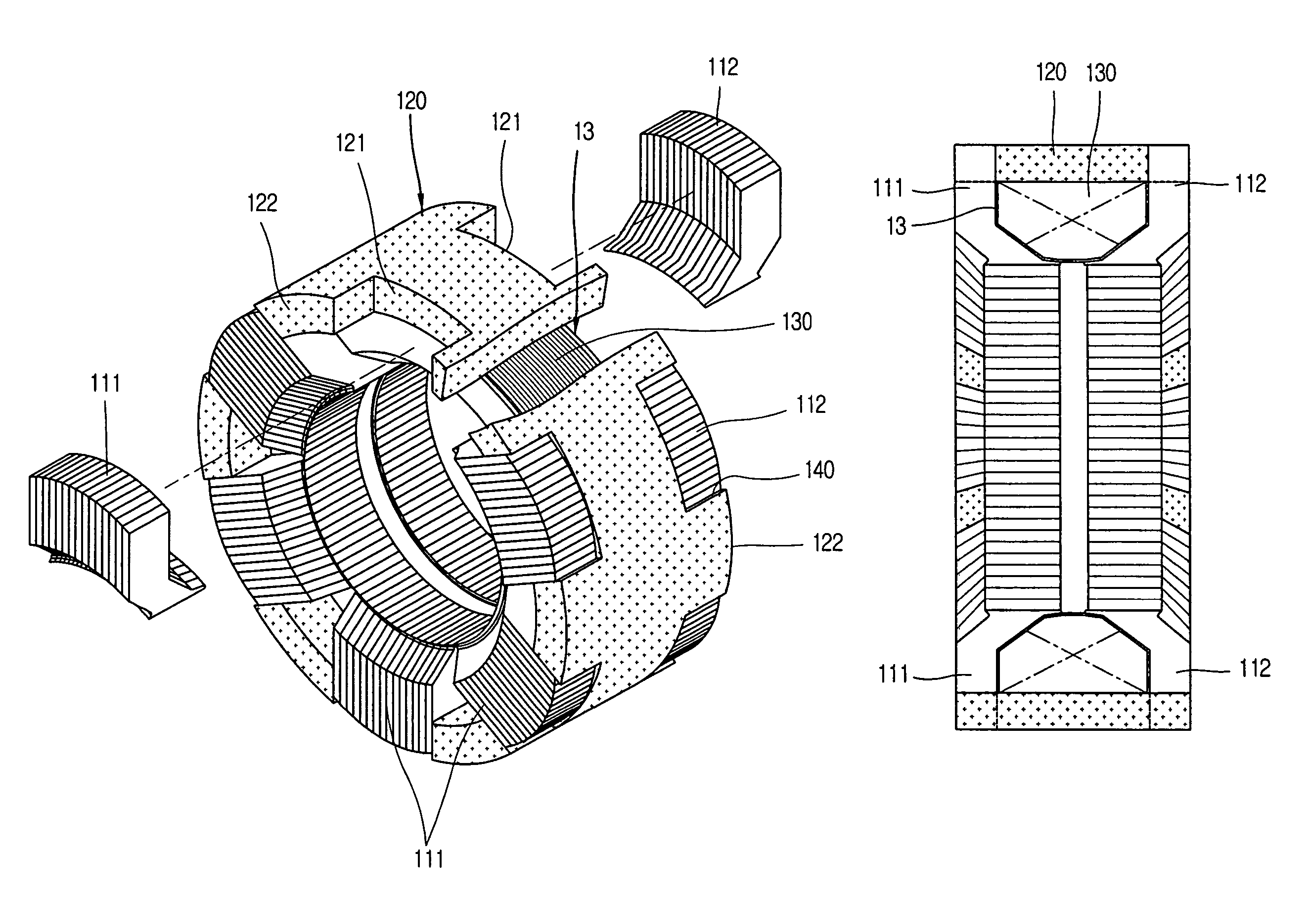
[0033]FIG. 4 is a partially-exploded perspective view showing an outer stator of a reciprocating motor in accordance with the present invention.

[0034]As shown, the outer stator of the reciprocating motor in accordance with the present invention includes: a bobbin 13 formed as a ring shape and provided with a winding coil 130 therein; an outer stator frame 120 coupled to an outer circumferential surface of the bobbin 13 and formed of a magnetic body in which a flux flows; a plurality of core blocks 111 coupled to the outer stator frame 120 and radially positioned at one side of the bobbin 13; a plurality second core blocks 112 coupled to the outer stator frame 120, facing the first core blocks 111, and positioned at the other side of the bobbin 13.

[0035]The bobbin 13 is formed as a ring shape whose outer circumferential surfa...


PUM


Abstract

An outer stator of a reciprocating compressor comprises: a bobbin formed as a ring shape and provided with a winding coil therein; an outer stator frame coupled to an outer circumferential surface of the bobbin and formed of a magnetic body in which a flux flows; a plurality of first core blocks coupled to the outer stator frame and positioned radially at one side of the bobbin; and a plurality of second core blocks coupled to the outer stator frame, facing the first core blocks, and positioned at the other side of the bobbin. Accordingly, deformation which may occur during manufacturing can be prevented, and a size of a motor can be minimized.

Description

BACKGROUND OF THE INVENTION[0001]1. Field of the Invention[0002]The present invention relates to a stator for a reciprocating motor, and particularly, to a stator of a reciprocating motor capable of preventing deformation of a stator, which occurs during its fixation, and of reducing a size of a motor by widening an area of a magnetic flux.[0003]2. Description of the Background Art[0004]In general, a motor is used as a core driving source for most electrical and electronic products such as compressors, washing machines and electric fans. A motor receives electric energy and converts the electric energy into kinetic energy. There are a lot of kinds of motors, and it may be classified into a rotary motor that converts electric energy to a rotary force, a reciprocating motor that converts electric energy to a linear movement force, and the like.[0005]Under circumstances of requiring a linear movement, the reciprocating motor which can implement a linear movement without any special equ...

Claims


Application Information

Patent Timeline
Patent Type & Authority Patents(United States)
IPC IPC(8): H02K1/18H02K33/00H02K35/00H02K41/00
CPCH02K33/18H02K15/02F04B13/00F04B17/04F04B39/00
Inventor LEE, HYUKJEONG, SANG-SUB
Owner LG ELECTRONICS INC
Why Eureka
Try Eureka