Imaging lens and imaging apparatus

a technology of imaging apparatus and focus lens, which is applied in the field of imaging lens, can solve the problems of affecting the magnification of the image, so as to achieve the effect of high maximum imaging magnification, suppressing the fluctuation of aberration during focusing, and reducing the weight of the focus lens group

Active Publication Date: 2018-06-14
FUJIFILM CORP
View PDF0 Cites 9 Cited by
  • Summary
  • Abstract
  • Description
  • Claims
  • Application Information

AI Technical Summary

Benefits of technology

[0038]According to the present invention, a lens system includes, in order from the object side, the first lens group having a positive refractive power, the second lens group, and the third lens group. In the lens system employing the floating focus system, configurations of the focus lens groups and configurations of the other lens groups are appropriately set, and predetermined conditional expressions are satisfied. Thereby, it is possible to provide an imaging lens, which has a high maximum imaging magnification and a small F number and in which the weights of the focus lens groups are reduced and fluctuation in aberration during focusing is suppressed such that high optical performance is maintained, and an imaging apparatus comprising the imaging lens.

Problems solved by technology

Particularly, in macro lenses, the amount of movement of the focus lens group tends to inevitably become large, and thus reduction in weight of the focus lens group has been an important issue.
Another important issue is suppression of fluctuation in aberration during focusing.
In the lens system described in JP2014-142601A, it is extremely difficult to suppress fluctuation in aberration, particularly, fluctuation in spherical aberration and coma aberration, caused by movement of the focus lens group.
In a case where it is intended to make the magnification higher than the maximum imaging magnification of the ordinary imaging lens, it is extremely difficult to correct the chromatic aberration at the time of close range imaging.

Method used


Image

  • Imaging lens and imaging apparatus
  • Imaging lens and imaging apparatus
  • Imaging lens and imaging apparatus

Examples


example 1

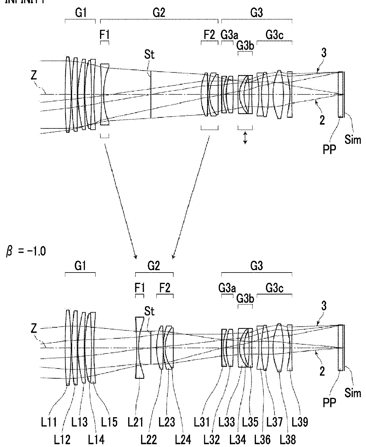
[0111]A lens configuration of an imaging lens of Example 1 is shown in FIG. 1, and an illustration method and a configuration thereof are as described above. Therefore, repeated description is omitted herein. The imaging lens of Example 1 includes, in order from the object side: a first lens group G1 that has a positive refractive power; a second lens group G2; and a third lens group G3 that has a negative refractive power. The first lens group G1 includes, in order from the object side, five lenses L11 to L15. The second lens group G2 includes, in order from the object side, a first focus lens group F1, an aperture stop St, and a second focus lens group F2. The first focus lens group F1 includes only a lens L21, and the second focus lens group F2 includes, in order from the object side, three lenses L22 to L24. During focusing from the object at infinity to the close-range object, the first focus lens group F1 moves to the image side, the second focus lens group F2 moves to the obj...

example 2

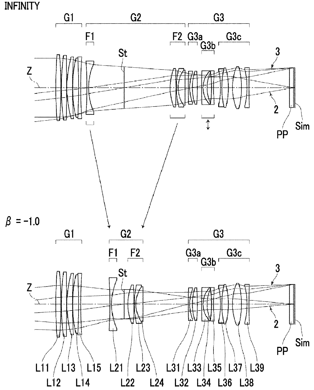
[0120]FIG. 2 shows a lens configuration of an imaging lens of Example 2. The imaging lens of Example 2 is the same as that of Example 1 in terms of: the group configuration; the signs of the refractive powers of the first lens group G1 and the third lens group G3; the lens groups moving during focusing and the direction of movement thereof; the vibration-proof lens group that performs image blur correction; the lens groups that remain stationary during image blur correction; and the number of lenses constituting each lens group. Table 3 shows basic lens data of the imaging lens of Example 2, Table 4 shows specification and variable surface spacings, and FIGS. 10 and 18 show aberration diagrams thereof. Here, FIG. 18 shows aberrations when image blur correction is performed by moving the vibration-proof lens group G3b by 0.44 mm in a case where there is image blurring which causes the optical axis to be inclined by 0.3 degrees on the lower side labeled as “image blur correction”.

TABL...

example 3

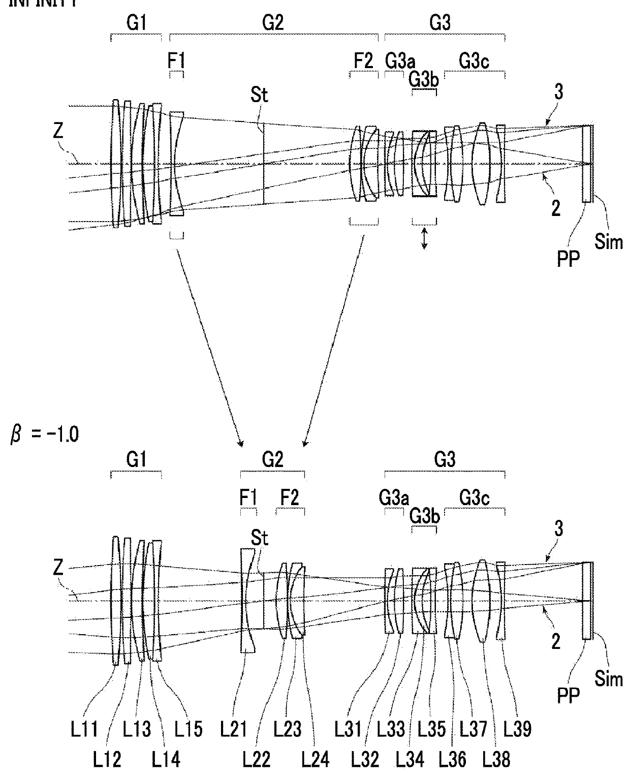
[0121]FIG. 3 shows a lens configuration of an imaging lens of Example 3. The imaging lens of Example 3 is the same as that of Example 1 in terms of: the group configuration; the signs of the refractive powers of the first lens group G1 and the third lens group G3; the lens groups moving during focusing and the direction of movement thereof; the vibration-proof lens group that performs image blur correction; the lens groups that remain stationary during image blur correction; and the number of lenses constituting each lens group. Table 5 shows basic lens data of the imaging lens of Example 3, Table 6 shows specification and variable surface spacings, and FIGS. 11 and 19 show aberration diagrams thereof. Here, FIG. 19 shows aberrations when image blur correction is performed by moving the vibration-proof lens group G3b by 0.46 mm in a case where there is image blurring which causes the optical axis to be inclined by 0.3 degrees on the lower side labeled as “image blur correction”.

TABL...


PUM


Abstract

The imaging lens consists of, in order from the object side, a first lens group having a positive refractive power, a second lens group, and a third lens group. In the second lens group, a first focus lens group having a negative refractive power is disposed to be closest to the object side, and a second focus lens group having a positive refractive power is disposed to be closest to the image side. During focusing, only the first and second focus lens groups move by changing the mutual spacing therebetween. The first lens group has two positive lenses and one negative lens. The first focus lens group consists of two or less lenses including a negative lens. Predetermined conditional expressions are satisfied.

Description

CROSS-REFERENCE TO RELATED APPLICATIONS[0001]The present application claims priority under 35 U.S.C. § 119 to Japanese Patent Application No. 2016-240060, filed on Dec. 12, 2016. The above application is hereby expressly incorporated by reference, in its entirety, into the present application.BACKGROUND OF THE INVENTION1. Field of the Invention[0002]The present invention relates to an imaging lens, which is suitable for a digital camera, a video camera, and the like, and an imaging apparatus which comprises the imaging lens.2. Description of the Related Art[0003]In the related art, in imaging lenses such as a digital camera, a so-called floating focus system is known in which focusing is performed by moving two or more lens groups with different loci. For example, JP2014-6487A, JP2014-142601A, JP2001-21798A, and JP2014-219601A disclose optical system employing a floating focus system in which a lens group closest to the object side and a lens group closest to the image side are made...

Claims


Application Information

Patent Timeline
Patent Type & Authority Applications(United States)
IPC IPC(8): G02B7/10G02B27/64G02B9/64
CPCG02B7/10G02B27/646G02B9/64G02B13/0035G02B13/009G02B15/143G02B15/22
Inventor KAWAMURA, DAIKIORI, TETSUYA
Owner FUJIFILM CORP
Why Eureka
Try Eureka