System and method for cooling a leading edge of a high speed vehicle

Active Publication Date: 2022-08-11
GENERAL ELECTRIC CO
View PDF6 Cites 0 Cited by
  • Summary
  • Abstract
  • Description
  • Claims
  • Application Information

AI Technical Summary

Benefits of technology

[0007]According to another exemplary embodiment, a leading edge assembly for a hypersonic vehicle, the leading edge assembly comprising: an outer wall tapering to a leading edge, the outer wall comprising a porous section, the porous section comprising a first porous region disposed at a stagnation point of the leading edge and a second porous region

Problems solved by technology

High speed vehicles often experience thermal management issues resulting from high heat load experienced during high speed operation, particularly at leading edges where the free air stream impinges on the vehicle.
Unmitigated

Method used


Image

  • System and method for cooling a leading edge of a high speed vehicle
  • System and method for cooling a leading edge of a high speed vehicle
  • System and method for cooling a leading edge of a high speed vehicle

Examples


embodiment 1

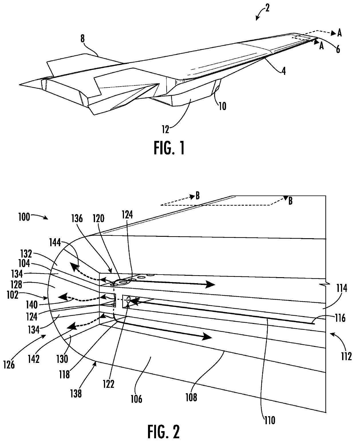
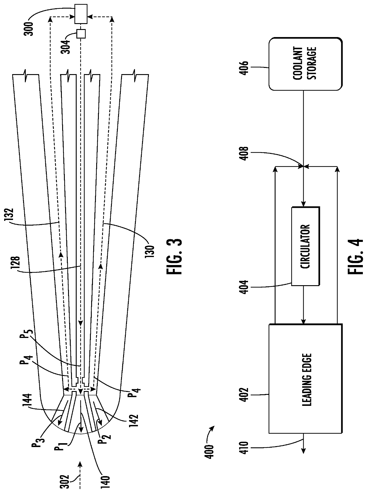
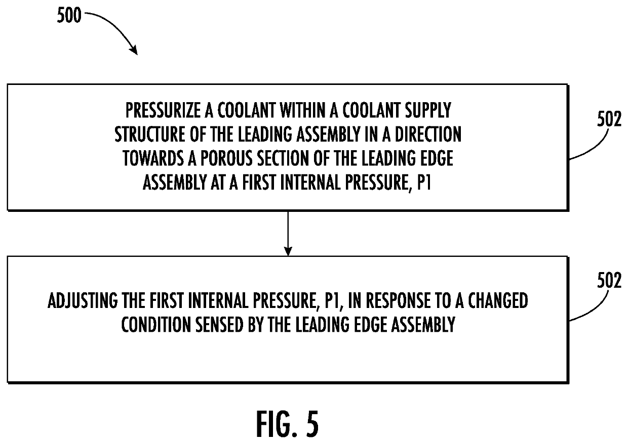
[0067] A leading edge assembly for a hypersonic vehicle, the leading edge assembly comprising: an outer wall tapering to a leading edge, the outer wall comprising a porous section, the porous section comprising a first porous region and a second porous region; a coolant supply structure defining a first supply flowpath extending to the first porous region and a second supply flowpath extending from the first supply flowpath at a location upstream of the first porous region to the second porous region; and a coolant supply for providing a flow of a coolant through the coolant supply structure and through the porous section to cool the outer wall.

embodiment 2

[0068] The leading edge assembly of any one of the embodiments, wherein the first porous region is disposed at a stagnation point of the leading edge, wherein the second porous region is disposed adjacent to the first porous region, and wherein the leading edge assembly is configured such that an internal pressure, P1, of the coolant at the first porous region is higher than an internal pressure, P2, of the coolant at the second porous region.

embodiment 3

[0069] The leading edge assembly of any one of the embodiments, wherein the second flowpath is configured to recirculate the coolant to an area corresponding with a heat removal device.


PUM


Abstract

A hypersonic aircraft includes one or more leading edge assemblies that are designed to manage thermal loads experienced at the leading edges during high speed or hypersonic operation. Specifically, the leading edge assemblies may include an outer wall tapered to a leading edge or stagnation point. The outer wall may define a vapor chamber and a capillary structure within the vapor chamber for circulating a working fluid in either liquid or vapor form to cool the leading edge. In addition, a dual-modal cooling structure can enhance heat transfer from the outer wall at the leading edge to the outer wall within the condenser section of the vapor chamber.

Description

FIELD[0001]The present subject matter relates generally to leading edge technologies for use in high speed vehicles, such as hypersonic aircraft.BACKGROUND[0002]High speed vehicles often experience thermal management issues resulting from high heat load experienced during high speed operation, particularly at leading edges where the free air stream impinges on the vehicle. For example, in an application involving hypersonic aircrafts, the leading edges can include the nose, engine cowls, and the leading edges of wings and stabilizers. Particularly when these vehicles are operating in the hypersonic speed range (e.g., Mach 5 or greater), the leading edges may be subjected to very high heat load (e.g., 500-1500 W / cm2) as the incident airflow passes through a bow shock and comes to rest at the vehicle surface, converting the kinetic energy of the gas to internal energy and greatly increasing its temperature. Unmitigated exposure to such thermal loading can result in component degradati...

Claims


Application Information

Patent Timeline
IPC IPC(8): B64C3/36B64C3/20
CPCB64C3/36B64C3/20
Inventor HOFER, DOUGLAS CARLRATHAY, NICHOLAS WILLIAMNATSUI, GREGORY ALEXANDERBOURASSA, COREY
Owner GENERAL ELECTRIC CO
Why Eureka
Try Eureka