Laminated glass, laminated safety glass, and method for the production thereof

a technology of laminated safety glass and laminated glass, which is applied in the direction of synthetic resin layered products, other domestic articles, protective garments, etc., can solve the problems of restricting the use of glass facade elements in particular in large surface area, and restricting so as to facilitate continuous production, optimize the freedom of facade design, and restrict the adhesion of composite materials

Active Publication Date: 2020-08-20
SEEN AG
View PDF0 Cites 3 Cited by
  • Summary
  • Abstract
  • Description
  • Claims
  • Application Information

AI Technical Summary

Benefits of technology

[0008]Although layer structures known from the prior art, for example from US 2009 / 0169795 A1, such as point-grid foils or woven fabrics coated on one side for light-absorption, can be used as interlayer in laminated safety glazing, they restrict adhesion of the composite and are amenable to continuous production only in restricted widths; this greatly restricts use in particular in large-surface-area glass facade elements. Coated woven fabrics can moreover only be produced with identical mesh apertures across the entire area of a glass pane. This is the starting point of the invention, which has the object of providing a laminated glass or laminated safety glass which on the one hand meets the most stringent safety requirements and on the other hand optimizes freedom in the design of facades or interiors.

Problems solved by technology

Although layer structures known from the prior art, for example from US 2009 / 0169795 A1, such as point-grid foils or woven fabrics coated on one side for light-absorption, can be used as interlayer in laminated safety glazing, they restrict adhesion of the composite and are amenable to continuous production only in restricted widths; this greatly restricts use in particular in large-surface-area glass facade elements.

Method used


Image

  • Laminated glass, laminated safety glass, and method for the production thereof
  • Laminated glass, laminated safety glass, and method for the production thereof
  • Laminated glass, laminated safety glass, and method for the production thereof

Examples


Embodiment Construction

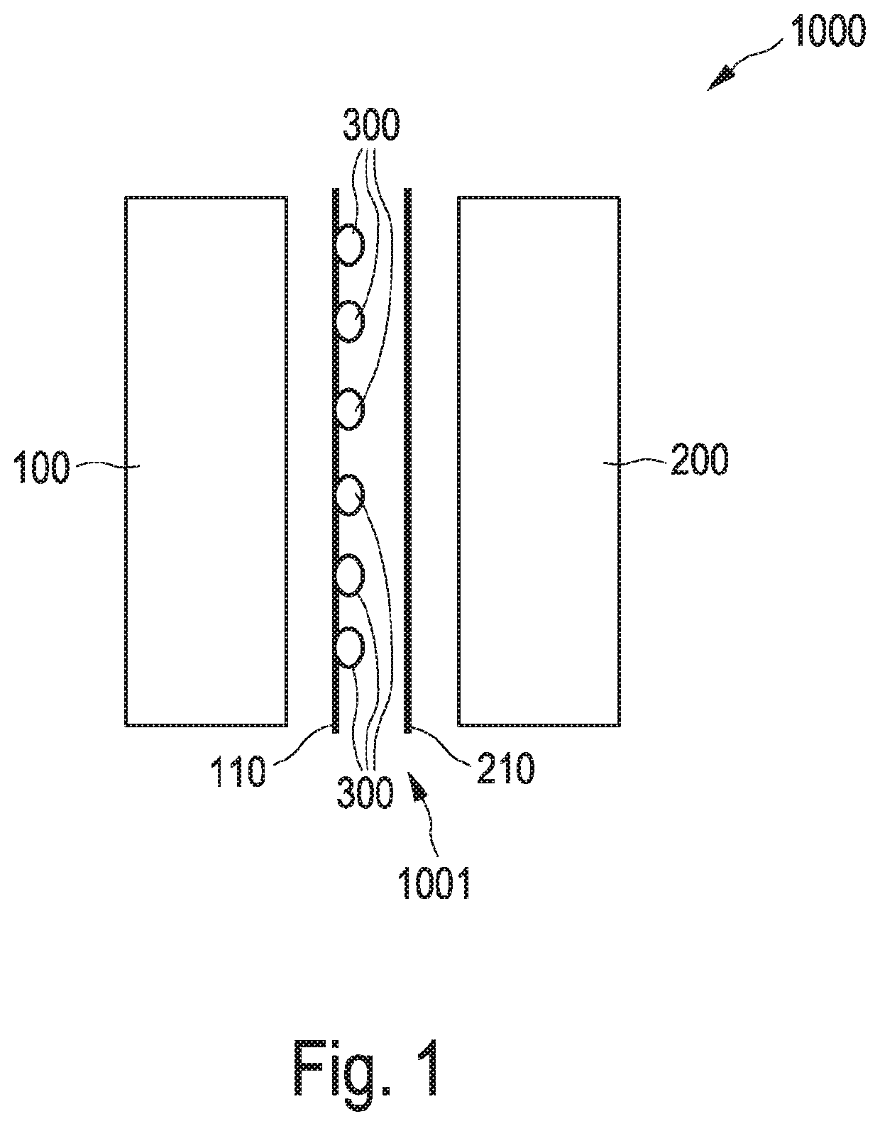
[0089]FIG. 1 is a diagram of the structure of an embodiment of a laminated glass 1000 in the first aspect of the invention. The laminated glass 1000 is shown here in a partial exploded view. The laminated glass 1000 comprises a first glass pane 100, and also a second glass pane 200. Arranged between the first glass pane 100 and the second glass pane 200 is a lamination foil composite 1001 with a first lamination foil 110 and a second lamination foil 210. The lamination foil composite has been bonded to the first and second glass pane 100, 200. Arranged between the first lamination foil 110 and the second lamination foil 210 is a large number of paillettes 300. Each of the paillettes here has a light-absorbing surface, and this light-absorbing surface faces toward the first lamination foil 110. The paillettes 300 in the embodiment shown have a layer structure comprising a decorative film and a light-absorbing layer, and also an adhesive layer which secures the paillettes on the first...


PUM

PropertyMeasurementUnit
distanceaaaaaaaaaa
sizeaaaaaaaaaa
thicknessaaaaaaaaaa

Abstract

A one-way laminated glass (1000, 2000, 3000, 4000, 5000, 6000A, 6000B, 6000C, 6000D) for installation in facades (6000, 7000) or for interior design, comprising a first and a second glass pane (100, 101, 102, 200, 201, 202), and also comprising, arranged between the first and second glass pane and bonded to these, a lamination foil composite (1001, 3001, 3002) with a first lamination foil (110, 111, 112, 113) and with a second lamination foil (210, 211, 212, 213), where
    • a large number of paillettes (300, 301, 302, 303, 304, 305, 500, 600A, 600B, 600C, 600D, 700) with a first light-absorbing surface (501) is arranged between the first lamination foil and second lamination foil, and a visual effect (E) is concomitantly achieved, where
    • the light-absorbing surface (501) of the paillettes faces toward the first lamination foil, and the paillettes are arranged at distances from one another such that when the laminated glass is viewed from the side corresponding to the light-absorbing surface (501) of the paillettes it appears transparent,
where a second surface (502) of the paillettes, which faces toward the second lamination foil, is optically reflective, and when the laminated glass is viewed from the side corresponding to the optically reflective surface (502) of the paillettes it appears less transparent.

Description

CROSS REFERENCE TO RELATED APPLICATION[0001]This is a continuation in part of 371 US national stage application of PCT / EP2018 / 072567 dated Aug. 21, 2018, the disclosure of which is incorporated by reference herein in its entirety as if set forth at length.BACKGROUND OF THE INVENTION[0002]The invention relates to a laminated glass, a laminated safety glass, a lamination foil arrangement, and also a process for the production of a lamination foil arrangement, of a laminated glass or of a laminated safety glass.[0003]The prior art has already disclosed one-way glazing and presentation materials. The one-way transparency effect arises because this glazing or these display panels has / have a monolaterally light-absorbing coated layer structure with a large number of apertures. When the interlayer is viewed from this light-absorbing side, it appears transparent; the other side is reflective, and from this side the material is therefore non-transparent. Layer structures of this type are des...

Claims


Application Information

Patent Timeline
Patent Type & Authority Applications(United States)
IPC IPC(8): B32B17/10
CPCB32B17/10761B32B17/10192B32B2307/402B32B17/1022B32B17/10357B32B2250/40B32B2307/412B32B2307/416B32B17/10247B32B17/10036B32B17/10045B32B7/12B32B27/08B32B2571/00B32B27/30B32B27/306B32B3/08B32B27/06B32B27/36B32B2307/5825B32B2250/05B32B2307/408B32B2250/04B32B27/40B32B2307/51B32B17/10935B32B17/10005B32B2367/00B32B3/085B32B17/10431B32B17/1055B32B17/10651B32B17/1088
Inventor SEIDLER, ROUVEN
Owner SEEN AG
Why Eureka
Try Eureka