

Rear fender assemblies for a work vehicle
- Summary
- Abstract
- Description
- Claims
- Application Information
AI Technical Summary
Benefits of technology
Problems solved by technology
Method used
Image

Examples
Embodiment Construction
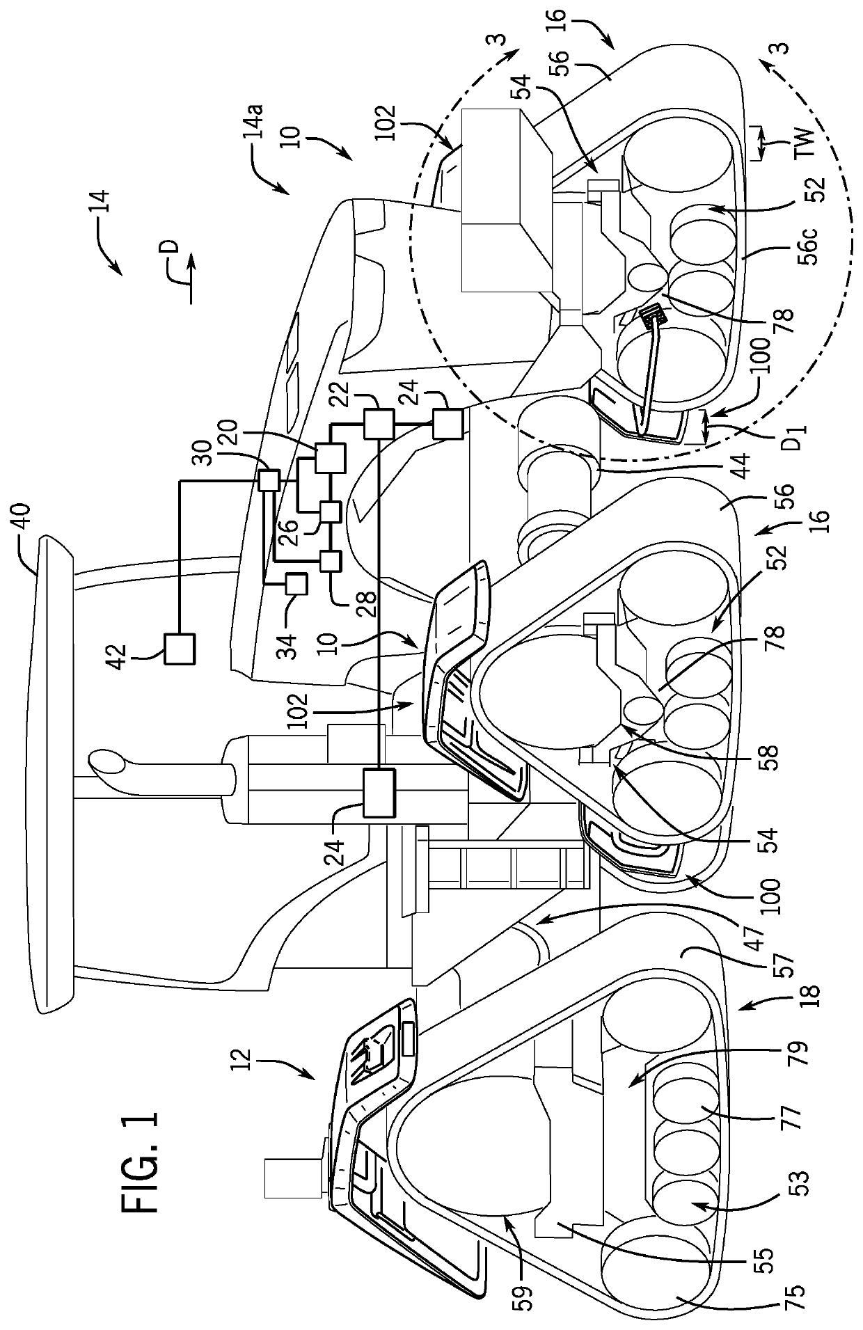
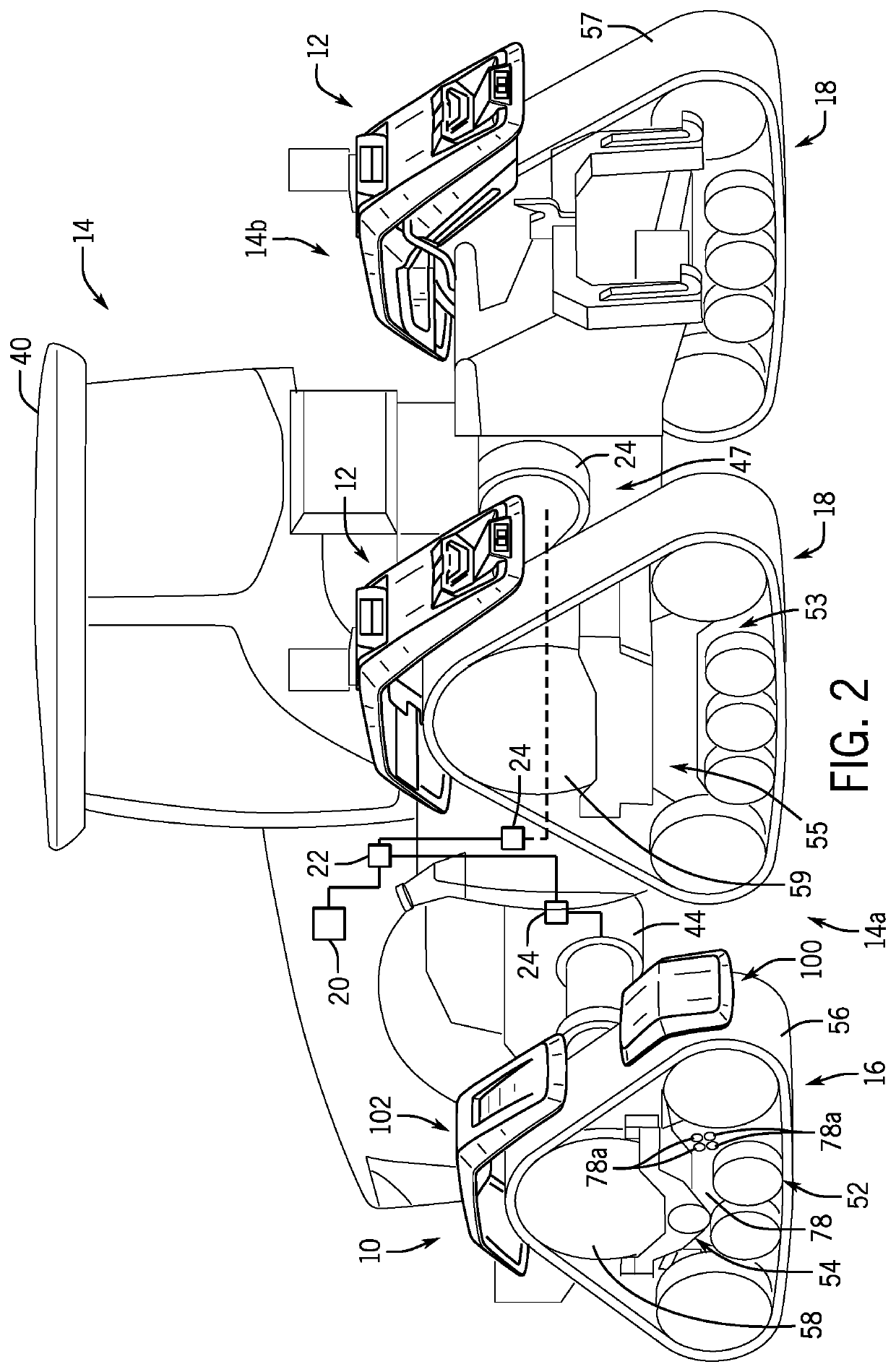
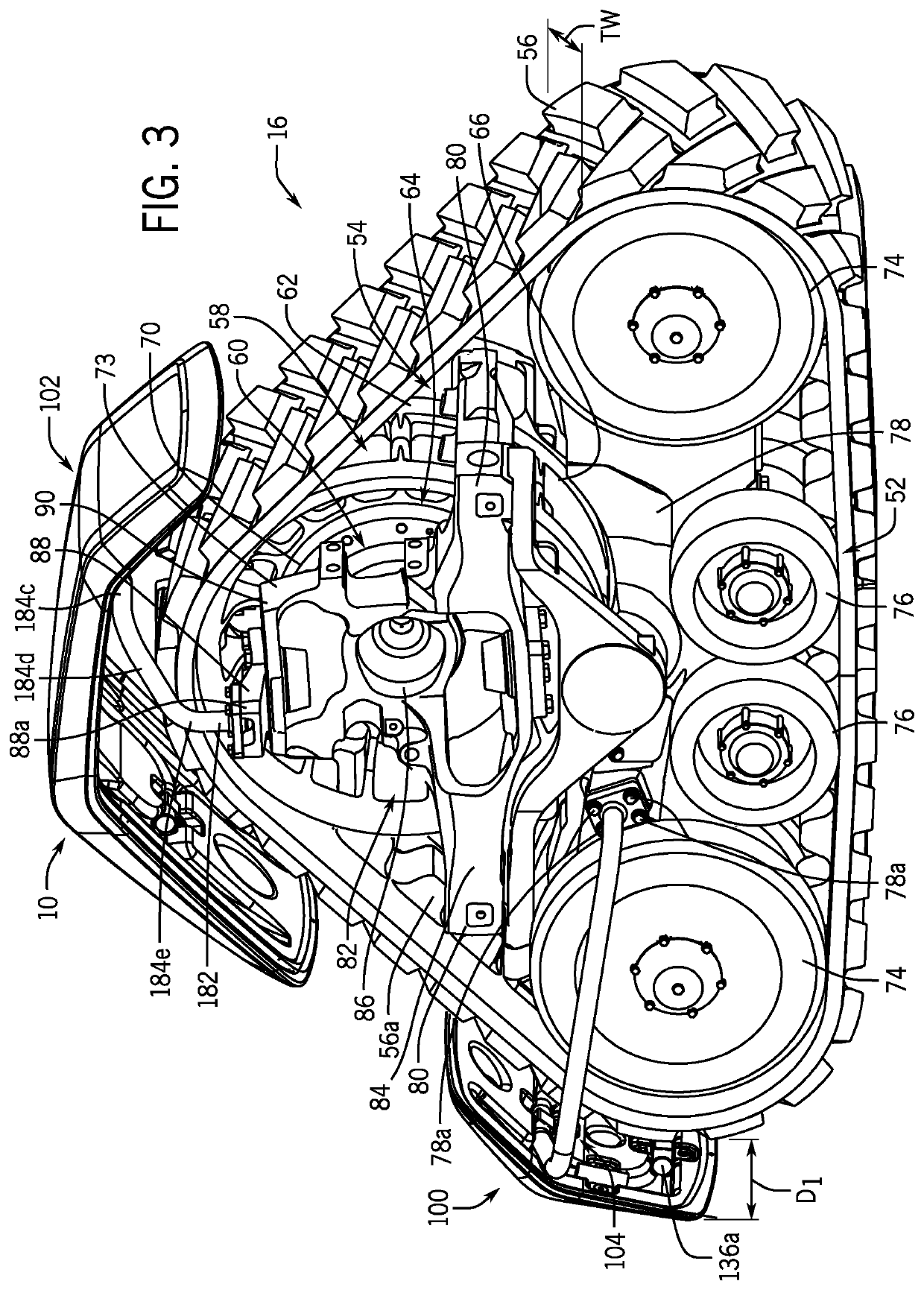
[0041]The following describes one or more example embodiments of the disclosed front fender assembly and rear fender assembly for a work vehicle, as shown in the accompanying figures of the drawings described briefly above. Various modifications to the example embodiments may be contemplated by one of skill in the art.
[0042]As used herein, unless otherwise limited or modified, lists with elements that are separated by conjunctive terms (e.g., “and”) and that are also preceded by the phrase “one or more of” or “at least one of” indicate configurations or arrangements that potentially include individual elements of the list, or any combination thereof. For example, “at least one of A, B, and C” or “one or more of A, B, and C” indicates the possibilities of only A, only B, only C, or any combination of two or more of A, B, and C (e.g., A and B; B and C; A and C; or A, B, and C).
[0043]As used herein, the term “axial” refers to a direction that is generally parallel to an axis of rotatio...
PUM
 Abstract
Description
Claims
Application Information