Supercharge Your Innovation With Domain-Expert AI Agents!

Slabbing Machine

a technology of slabbing machine and reel, which is applied in the direction of thin material handling, metal working apparatus, filament handling, etc., can solve the problems of manual process, laborious, manual process, etc., and achieve the effect of removing the material wound around the reel, easy, efficient and automati

Active Publication Date: 2020-08-20
PROD SOLUTIONS INT LLC
View PDF0 Cites 0 Cited by
  • Summary
  • Abstract
  • Description
  • Claims
  • Application Information

AI Technical Summary

Benefits of technology

The present invention is a slabbing machine that improves on existing technology by making it easier, more efficient, and automatic to remove material wound around a reel. The machine does not require any manual interaction.

Problems solved by technology

The producer of such reels is often encountered with reels of material where either the material is defective due to poor printing, poor coating, wrinkles or other issues.
Removing the web material from the reel is tedious if carried out manually, because the web material is wound tightly in many layers and is often too thick to be cut in one go.
Altogether, the manual process is slow, laborious and there is an inherent risk of injury for a number of reasons.
Commonly injuries occur due to the manipulation of a sharp knife or due to repeated use of a hand knife, which often results in wrist, elbow or shoulder muscular or skeletal problems.

Method used


Image

  • Slabbing Machine
  • Slabbing Machine
  • Slabbing Machine

Examples


Embodiment Construction

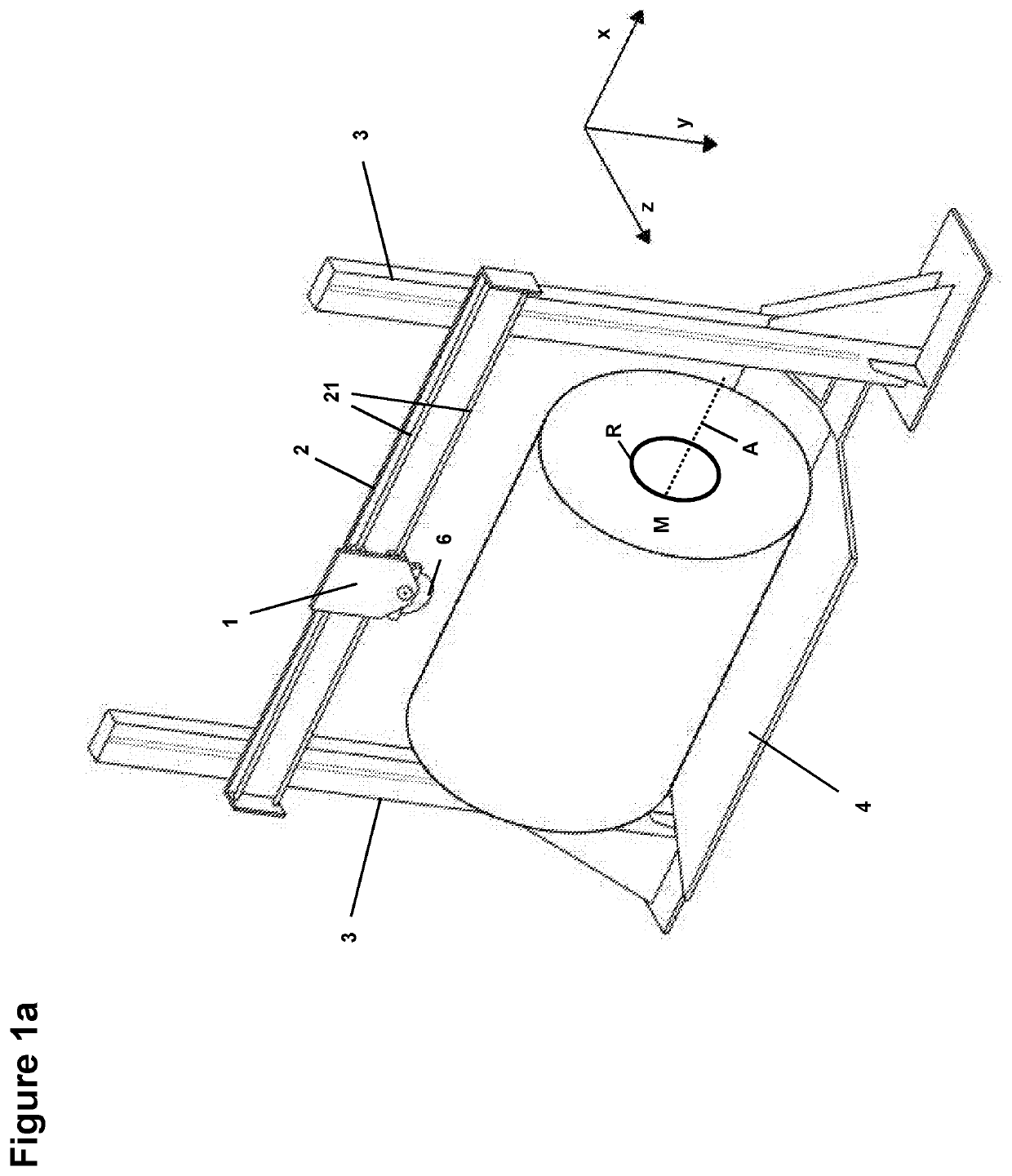
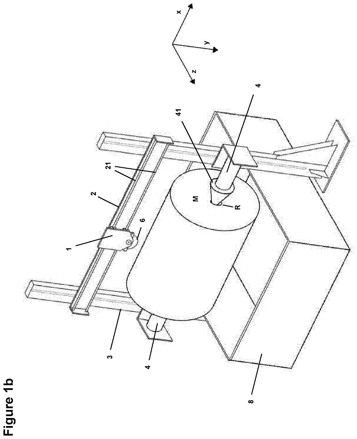
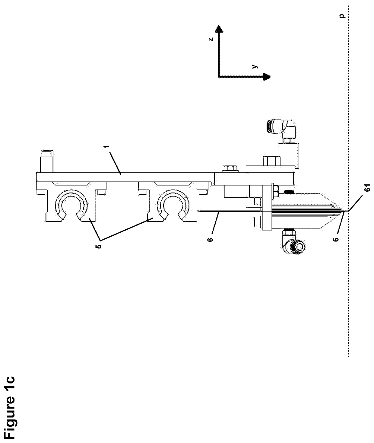
[0013]The slabbing machine comprises a frame 3 and a structure 4 connected to the frame 3 for firmly holding a reel R, around which a material M is wound, in a way preventing any movement of the reel R relative to the frame 3 (FIGS. 1a-b). A beam 2 is connected to the frame 3 and is displaceable along the frame 3 in a radial direction y, from one end position to the other end position and back. A blade holder 1 is connected to the beam 2 and displaceable along the beam 2 in a longitudinal direction x perpendicular to the radial direction y (in both ways). A blade 6 is mounted on the blade holder 1 for cutting the material M down to a cutting plane p (FIG. 1c). This cutting plane p is perpendicular to the radial direction y and located at the farthest end 61 of the blade 6 in radial direction y, i.e. the end 61 of the blade 6 which is the nearest to the reel R and which will cut the material M. The structure 4 holds the central longitudinal axis A of the reel R in the plane defined b...


PUM


Abstract

Slabbing machine for removing material M wound around a reel R, comprising a frame; a structure for holding the material M wound around the reel R; a beam connected to the frame and displaceable along the frame in a radial direction y; a blade holder connected to the beam and displaceable along the beam in a longitudinal direction x perpendicular to the radial direction y; a blade mounted on the blade holder for cutting the material M down to a cutting plane p perpendicular to the radial direction y and located at the farthest end of the blade in radial direction y; wherein one or several air outlets are mounted on the blade holder 1 and directed towards the cutting plane p for blowing air towards the cutting plane p.

Description

FIELD OF THE INVENTION[0001]The present invention relates to a slabbing machine for removing material wound around a reel.BACKGROUND OF THE INVENTION[0002]In many industries web material is used and provided on reels around which the material is wound tightly. The producer of such reels is often encountered with reels of material where either the material is defective due to poor printing, poor coating, wrinkles or other issues. In these cases, in order to allow recycling or disposal to landfill the web material must be removed from the reel, which can also be recycled if it is not defective, i.e. in the case of paper.[0003]Removing the web material from the reel is tedious if carried out manually, because the web material is wound tightly in many layers and is often too thick to be cut in one go. An operator seeking to remove the web material from the reel has to cut a small number of layers at a time and repeat the operation many times. In addition to cutting through the layers of...

Claims


Application Information

Patent Timeline
IPC IPC(8): B65H73/00B26D7/18B26D1/16
CPCB26D1/16B26D7/1854B65H73/00B26D2210/11B26D2007/0018
Inventor FREEDMAN, MELVINLANDWEHR, THOMAS
Owner PROD SOLUTIONS INT LLC
Features
  • R&D
  • Intellectual Property
  • Life Sciences
  • Materials
  • Tech Scout
  • Unparalleled Data Quality
  • Higher Quality Content
  • 60% Fewer Hallucinations
Learn More