Photonic radio-frequency receiver with mirror frequency suppression function

a radio frequency receiver and mirror technology, applied in the field of photoelectric technology, can solve the problems of mirror frequency interference in heterodyne structures, affecting the quality of the received signal of the system, and affecting the quality of the radio frequency signal to be tested, so as to achieve a more compact system structure.

Active Publication Date: 2020-08-20
ZHEJIANG UNIV
View PDF0 Cites 16 Cited by
  • Summary
  • Abstract
  • Description
  • Claims
  • Application Information

AI Technical Summary

Benefits of technology

[0027]In the present disclosure, the laser, the dual-electrode modulator, the optical coupler, the third photoelectric detector, the electric filter and the electric amplifier form a photoelectric loop, i.e. the photoelectric oscillator. In the present disclosure, the single dual-electrode modulator is combined with the photoelectric oscillator to realize the dual input of the radio-frequency signal and the local oscillator signal, thereby allowing a more compact system structure. The photoelectric oscillator is utilized to generate the optically generated local oscillator signal, thus eliminating the need for an external high-quality and low-phase-noise local oscillator. The photonic mirror frequency suppression function is realized by setting a bias point for the dual-electrode modulator, utilizing the beat frequencies at the upper and lower sidebands in the optical domain and combining the orthogonal electric coupler. The present disclosure is suitable for systems such as wireless communication, radar, electronic warfare systems and the like.

Problems solved by technology

However, heterodyne structures have the problem of mirror frequency interference.
When the input signal contains radio-frequency and mirror-frequency signals (the mirror frequency and the radio frequency are symmetrical with respect to the local oscillation frequency), the radio-frequency signal and the mirror-frequency signal will be down-converted to the same intermediate frequency signal at the same time, while the intermediate frequency signal down-converted by the mirror-frequency signal cannot be filtered out due to spectral aliasing, thus distorting the radio-frequency signal to be tested and affecting the quality of the received signal of the system.
However, a filter with high roll-off factor is hardly achievable for both electric and optical filters, so this method is not suitable for wide-band signals or low intermediate frequency signals.

Method used


Image

  • Photonic radio-frequency receiver with mirror frequency suppression function

Examples


Embodiment Construction

[0032]In order to make the object, technical solution and advantages of the present disclosure more comprehensible, the present disclosure is further described below with reference to the accompanying drawings and the embodiments. It should be understood that the specific embodiments described herein are only used to explain the present disclosure and are not intended to limit the scope of the present disclosure.

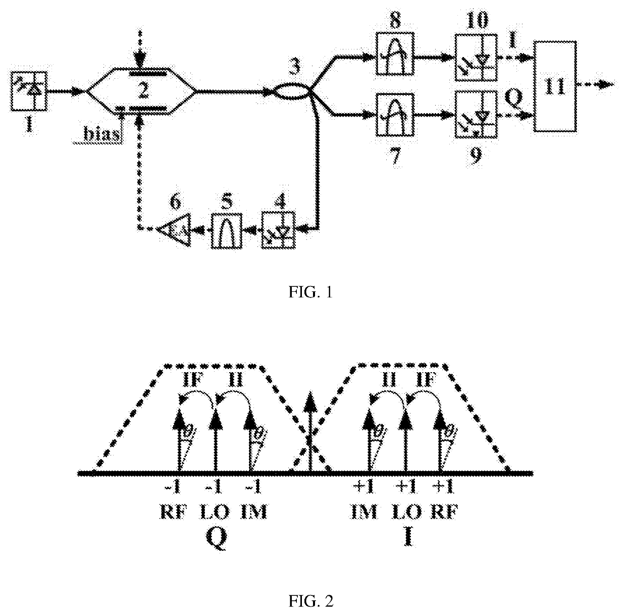
[0033]As shown in FIG. 1, the photonic radio-frequency receiver capable of mirror frequency suppression as specified in the present disclosure comprises a laser 1, dual-electrode modulator 2, optical coupler 3, photoelectric detector 4, electric band-pass filter 5, electric amplifier 6, optical filter 7, optical filter 8, photoelectric detector 9, photoelectric detector 10, and orthogonal electric coupler 11.

[0034]The laser 1, the two-electrode modulator 2, the optical coupler 3 and the photoelectric detector 4 are sequentially connected through optical fiber cables; the pho...


PUM


Abstract

A photonic radio-frequency receiver with mirror frequency suppression function, in which a single modulator is utilized to form a photoelectric oscillator so as to generate high-quality and low-phase-noise optically generated local oscillators, without the need for an external local oscillator source, and at the same time, another radio-frequency port is used as a radio-frequency signal input port, thereby allowing a compact structure. By properly setting a bias point for the two-electrode modulator and orthogonally synthesizing two branches of intermediate frequency signals respectively generated by the upper and lower sideband beat frequencies of the modulated optical signal, the photonic radio-frequency receiver realizes the functions of receiving radio-frequency signals and suppressing mirror frequency signals. The present disclosure can realize a photonic mirror-frequency suppression receiver.

Description

CROSS REFERENCE OF RELATED APPLICATIONS[0001]The present application claims the benefit of China Patent Application No. 201910114554.7, entitled “PHOTONIC RADIO-FREQUENCY RECEIVER WITH MIRROR FREQUENCY SUPPRESSION FUNCTION” filed on Feb. 14, 2019, in the China National Intellectual Property Administration, the entire content of which is incorporated herein in its entirety.TECHNICAL FIELD[0002]The present disclosure belongs to the field of photoelectric technology and particularly relates to a photonic radio-frequency receiver with mirror frequency suppression function.BACKGROUND[0003]With the rapid development in the field of wireless communication electronic technology, wireless communication has increasingly higher requirements for the integration and flexibility of receivers, the compatibility of communication systems, the engineering application and other aspects. Radio-frequency receivers are the core structure of microwave radio-frequency systems such as wireless communication...

Claims


Application Information

Patent Timeline
Patent Type & Authority Applications(United States)
IPC IPC(8): H04B10/61H04B10/2575H04B10/50
CPCH04B10/503H04J14/06H04B10/616H04B10/25752G01R29/26G01B9/02H04B10/50H04B10/00H04B2210/006
Inventor JIN, XIAOFENGXIAO, KANGQIU, JICHENJIN, XIANGDONGYU, XIANBINTAN, QINGGUICONG, BO
Owner ZHEJIANG UNIV
Why Eureka
Try Eureka