Supercharge Your Innovation With Domain-Expert AI Agents!

Lidar system including convection cooling

a convection cooling and lidar technology, applied in the field of lidar systems, can solve the problems of increasing complexity and cost, and achieve the effect of reliable and efficient cooling and reliable operation of the lidar system

Active Publication Date: 2020-08-27
ROBERT BOSCH GMBH
View PDF0 Cites 3 Cited by
  • Summary
  • Abstract
  • Description
  • Claims
  • Application Information

AI Technical Summary

Benefits of technology

The LIDAR system described in this patent has the benefit of having automatic cooling that starts when the components are spinning and stops when the system is shut off. This ensures that the system always operates reliably and efficiently.

Problems solved by technology

However, such an external cooling device has the disadvantage that an additional power source is necessary, thus increasing the complexity and the costs.

Method used


Image

  • Lidar system including convection cooling
  • Lidar system including convection cooling
  • Lidar system including convection cooling

Examples


Embodiment Construction

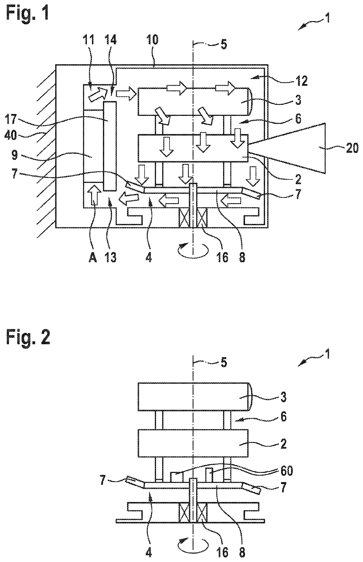
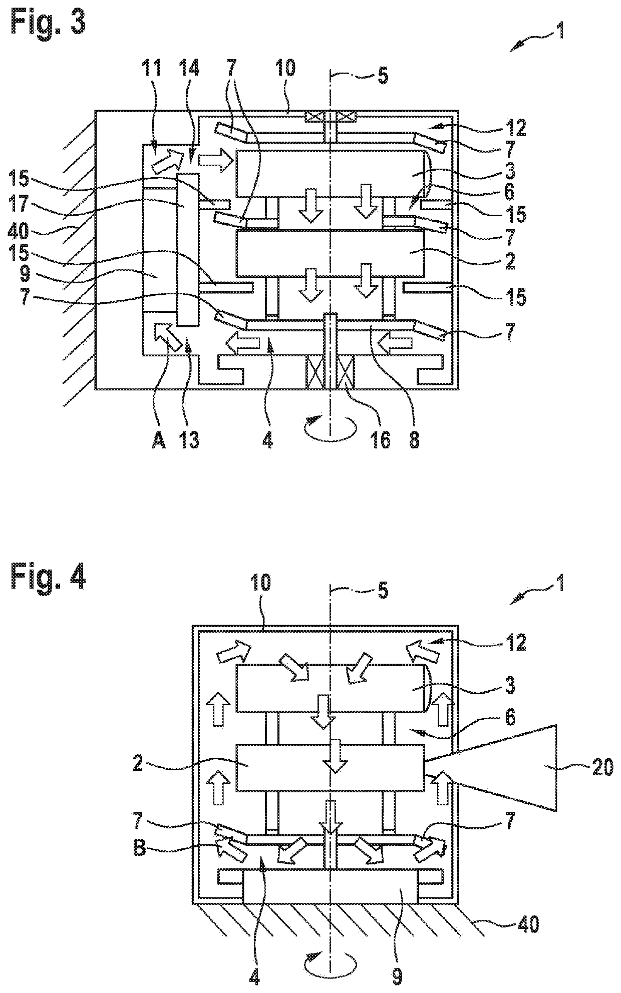
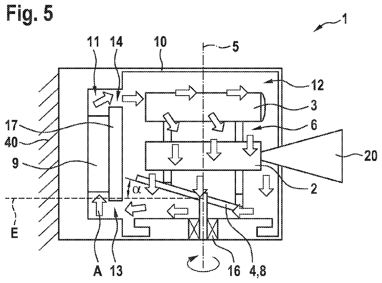
[0026]FIGS. 1 and 2 show a LIDAR system 1 according to a first exemplary embodiment of the present invention. LIDAR system 1 illustrated in FIG. 1 includes a laser unit 2, a receiving unit 3, and a cooling device 4 that are jointly situated on a rotation element 6 and rotate about a shared rotational axis 5. In the first exemplary embodiment, cooling device 4 includes a control board 8 that is configured for controlling LIDAR system 1, and at which vane elements 7 are situated. A laser beam 20 for scanning the surroundings is emitted, for example, by laser unit 2 perpendicularly with respect to the rotational axis.

[0027]The first exemplary embodiment also includes a housing 10 with a working area 12, and a cooling area 11 in which a heat exchanger 9 is situated and which is in contact with working area 12 via an inlet area 13 and an outlet area 14 and separated from working area 12 by a wall 17. Housing 10 may be mounted at a vehicle 40, for example, at an outer side. Due to the rot...


PUM


Abstract

A LIDAR system that includes a laser unit, a receiving unit, and a cooling device for generating a cooling airflow. The laser unit, the receiving unit, and the cooling device are situated rotatingly about a rotational axis, so that the cooling airflow for cooling the rotating components is generated by the LIDAR system itself.

Description

FIELD[0001]The present invention relates to a LIDAR system. In particular, the present invention relates to a LIDAR system in which a defined cooling airflow for efficient cooling of the rotating components is generated.BACKGROUND INFORMATION[0002]LIDAR systems are used for surroundings detection in motor vehicles. A LIDAR system includes a laser and a receiving unit which are generally situated on a rotation element. Lasers having comparatively high optical powers, and thus likewise high thermal powers, are used in such applications. To avoid harmful effects on the components, such as malfunctions or functional restrictions, efficient dissipation of the heat from the components is necessary. This may take place passively, for example, with the aid of heat conduction to the carrier system. In addition, it is possible to use active cooling methods. Such an active cooling method is described in German Patent Application No. DE 102012110584 A1. A sensor device, such as a radar system o...

Claims


Application Information

Patent Timeline
Patent Type & Authority Applications(United States)
IPC IPC(8): G01S7/481H05K7/20
CPCH05K7/202G01S7/4813G01S17/42G01S7/4817
Inventor HATTASS, MIRKOZOELLER, MICHAELGREINER, ALEXANDERHAS, REMIGIUS
Owner ROBERT BOSCH GMBH
Features
  • R&D
  • Intellectual Property
  • Life Sciences
  • Materials
  • Tech Scout
  • Unparalleled Data Quality
  • Higher Quality Content
  • 60% Fewer Hallucinations
Learn More