Film forming apparatus, film forming method, and method for manufacturing solar cell

A film-forming device and film-forming technology, applied in the direction of final product manufacturing, sustainable manufacturing/processing, circuits, etc., to achieve efficient cooling, reliable temperature drop, and the effect of suppressing the influence of films on other layers of the film-forming target substrate

Inactive Publication Date: 2018-03-13
ULVAC INC
View PDF3 Cites 2 Cited by
  • Summary
  • Abstract
  • Description
  • Claims
  • Application Information

AI Technical Summary

Problems solved by technology

[0009] In addition, the above-mentioned problem occurs not only when a metal layer is formed on a substrate for film formation of a heterojunction solar cell, but also when a sputtered film made of metal is formed on a substrate for film formation.

Method used


Image

  • Film forming apparatus, film forming method, and method for manufacturing solar cell
  • Film forming apparatus, film forming method, and method for manufacturing solar cell
  • Film forming apparatus, film forming method, and method for manufacturing solar cell

Examples


Embodiment Construction

[0059] Embodiments of the present invention will be described in detail below with reference to the drawings.

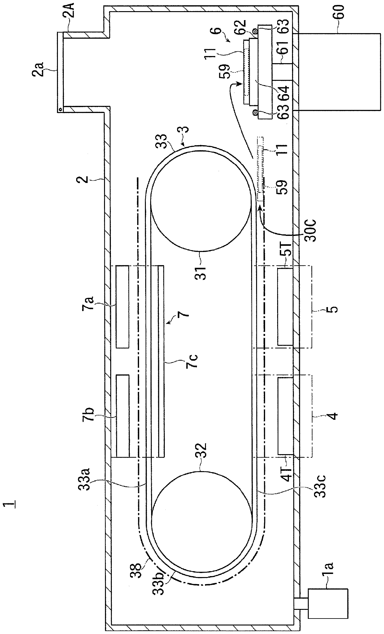
[0060] figure 1 It is a schematic configuration diagram showing the whole of an embodiment of the film forming apparatus according to the present invention.

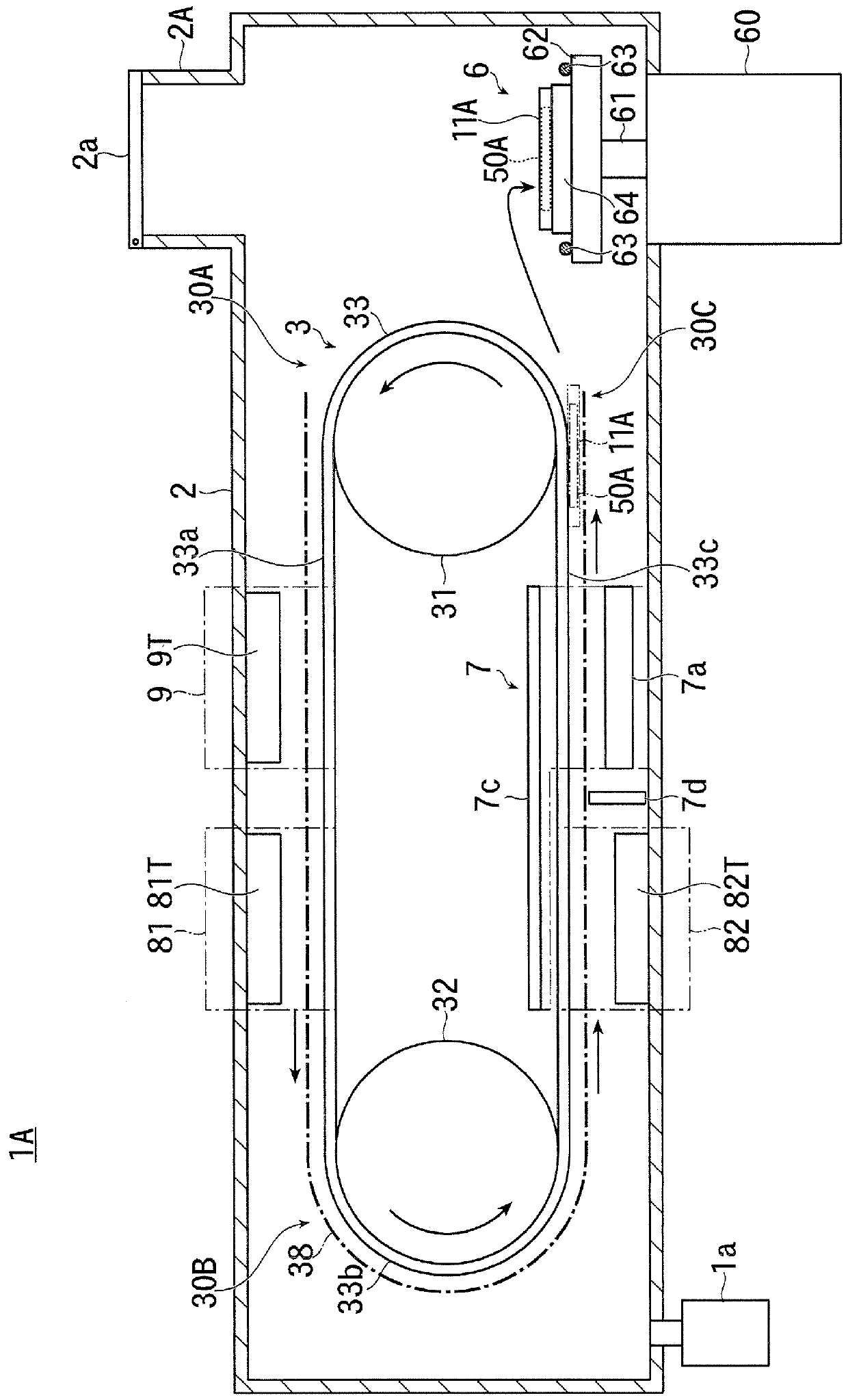
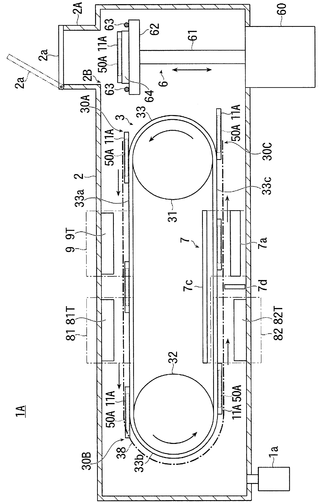
[0061] also, figure 2 is a plan view showing a schematic configuration of the substrate holder transport mechanism in this embodiment, image 3 It is a front view showing main parts of the substrate holder transport mechanism in this embodiment.

[0062] and, Figure 4 (a) to Figure 4 (c) shows the structure of the substrate holder used in this embodiment, Figure 4 (a) is a top view of a state where the substrate to be film-formed (hereinafter referred to as "substrate") is not held, Figure 4 (b) is a top view of the state holding the substrate, Figure 4 (c) is Figure 4 (a) A-A line sectional view.

[0063] also, Figure 5 (a), Figure 5 (b) shows the structure of the conveyance return part of ...


PUM


Abstract

The present invention provides technique capable of performing efficient and reliable cooling when a metal layer is formed on a to-be-coated substrate by sputtering. A substrate holder transport mechanism (3) is provided in a vacuum tank (2) formed with a single vacuum atmosphere, and the substrate holder transport mechanism (3) has an out-side transfer section (33a) for transporting a substrate holder (11) for holding a to-be-coated substrate (50) to a predetermined direction along a transportation path, an in-side transfer section (33c) for transporting the substrate holder (11) along the path in a direction opposite to the transport direction of the out-side transfer section (33a), and a transport folding section (30B) returns the substrate holder (11) from the out-side transfer section(33a) to the in-side transfer section (33c) while maintaining the vertical relationship. The out-side transfer portion (33a) passes through a cooling region (7) and the in-side transfer portion (33c)passes through first and second metal layer deposition regions (4, 5).

Description

technical field [0001] The present invention relates to the technology of a film forming apparatus for forming a film on one surface of a substrate by sputtering in a vacuum, and in particular to the technology of forming a metal layer on one surface of a substrate for a heterojunction solar cell. Background technique [0002] In recent years, solar cells have been put into practical use as clean and safe energy sources, and among them, heterojunction type solar cells have attracted attention. [0003] Heterojunction solar cells have higher conversion efficiency than monocrystalline silicon solar cells, and because they use an amorphous silicon layer, they have advantages such as being able to reduce the amount of silicon used. [0004] In recent years, a so-called rear contact structure has been proposed as a heterojunction solar cell that does not have an electrode on the light receiving surface but has a back electrode on the back surface opposite to the light receiving s...

Claims


Application Information

Patent Timeline
Patent Type & Authority Applications(China)
IPC IPC(8): C23C14/56C23C14/34C23C14/54C23C14/16C23C14/08H01L31/0224
CPCC23C14/08C23C14/165C23C14/3464C23C14/541C23C14/568H01L31/022425Y02E10/50Y02P70/50
Inventor 松崎淳介高桥明久
Owner ULVAC INC
Why Eureka
Try Eureka