Supercharge Your Innovation With Domain-Expert AI Agents!

Phase change module and electronic device mounted with same

A phase change and heat sink technology, applied in the direction of electric solid devices, circuits, electrical components, etc., can solve the problems of unclear structure, no mention, no consideration of thermal conductivity, etc., to achieve low cost, high efficiency and reliability cooling effect

Inactive Publication Date: 2015-04-29
HITACHI LTD
View PDF10 Cites 3 Cited by
  • Summary
  • Abstract
  • Description
  • Claims
  • Application Information

AI Technical Summary

Problems solved by technology

[0014] In the prior art mentioned above, in Patent Document 1 to Patent Document 5, the structure in the case where the evaporating part overlaps with the condensing part becomes unclear, and the magnitude of the thermal conductivity that governs the phase transition is neither mentioned nor considered. A structure in which the vapor flow and liquid return flow do not affect each other

Method used


Image

  • Phase change module and electronic device mounted with same
  • Phase change module and electronic device mounted with same
  • Phase change module and electronic device mounted with same

Examples


Embodiment 1

[0050] (basic structure)

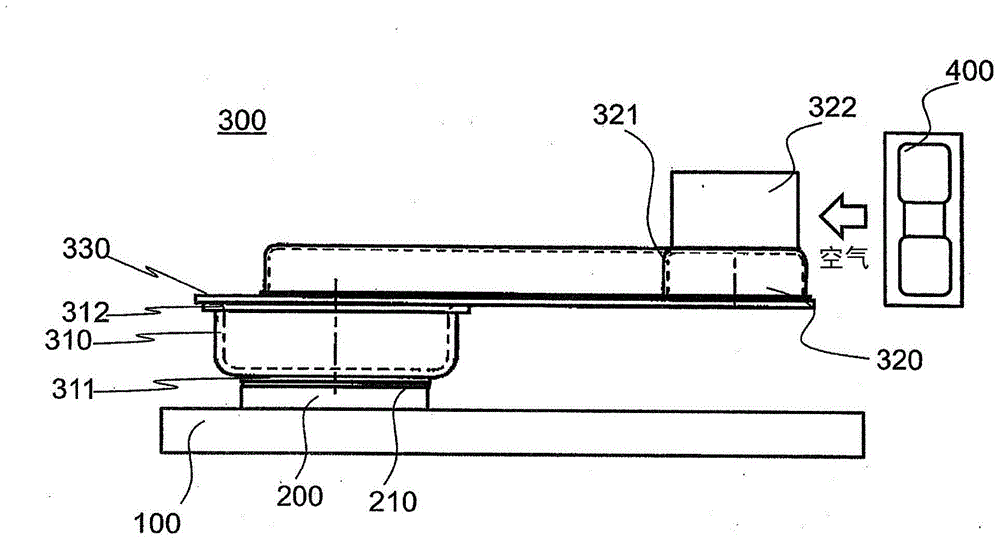
[0051] figure 1The overall structure viewed from the side around the phase change module 300 using thermosyphon is shown. In the drawings, reference numeral 100 denotes a circuit board on which a semiconductor device 200 as a heat source such as a CPU is mounted. Furthermore, a heat receiving sheath 310 constituting a part of the phase change module 300 utilizing thermosiphon of the present invention is mounted on the surface of the semiconductor device 200 . The heat receiving sheath 310 is composed of a boiling heat conducting surface 311 and a sheath shell 312 . The boiling heat transfer surface 311 is fixed to the sheath shell 312 by brazing or the like. More specifically, a so-called thermal grease 210 is applied on the surface of the semiconductor device 200 to ensure good thermal bonding with the boiling heat transfer surface 311, and the bottom surface of the above boiling heat transfer surface 311 is brought into contact with the surface a...

Embodiment 2

[0060] (with a core on the connecting plate)

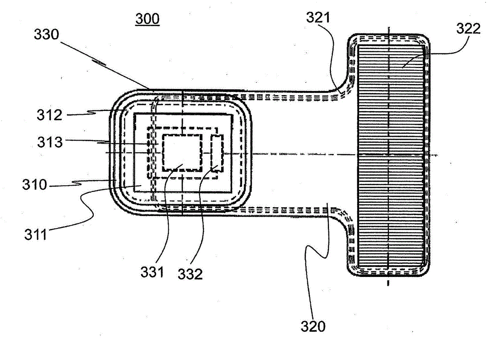
[0061] Figure 4 A side view of a phase change module 300 for increasing heat tolerance is shown as another embodiment. A core member 333 is provided on the connecting plate 330 . The core member 333 is constituted by a twisted wire of thin metal wires, a netted metal net, or the like. The length of the core member 333 is the length from the position of the fin 322 of the condenser 320 to a liquid return hole (not shown). By providing the core member 333, the high-speed flow of the refrigerant vapor will not hinder the flow of the liquid return, but the refrigerant liquid can be guided to the liquid return hole. Thereby, the coolant can be sufficiently supplied to the boiling heat transfer surface 311, and the allowable amount of heat received from the semiconductor device can be increased.

Embodiment 3

[0063] (with threaded holes on the connecting plate)

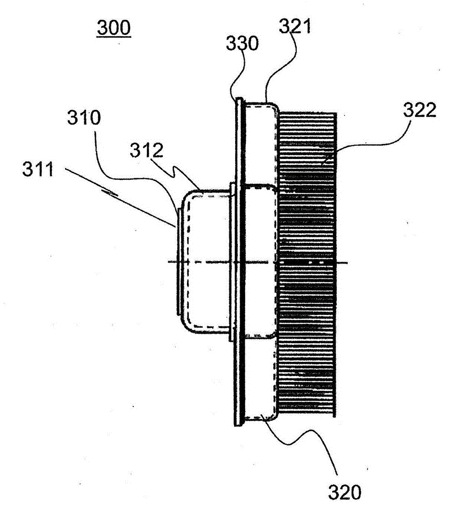
[0064] Figure 5 A side view of a phase change module 300 in consideration of mounting on a semiconductor device is shown as another embodiment. The connecting plate 330 is provided with a screw mounting hole 340 for mounting to a semiconductor device. The screw mounting holes 340 are provided at positions corresponding to the screw holes provided in the circuit board. Accordingly, the phase change module 300 can be stably mounted on the semiconductor device.


PUM


Abstract

To provide a phase change module as a cooling system capable of saving energy and miniaturizing of the cooling system utilizing a thermo siphon, and an electronic device suitable to mounting such a phase change module. The phase change module 300 includes a jacket case 312 attached with an evaporator surface 311 with the evaporator surface 311 being arranged on a heat generating body, a radiator case 321 attached with cooling fins (radiator) 322 arranged at a position departing from the heat generating body, and a connecting plate 330 that connects the jacket case 312 and the radiator case 321, in which holes are bored in the connecting plate 330 at a position where the jacket case 312 and the radiator case 321 overlap.

Description

technical field [0001] The present invention relates to a cooling system for an electronic device such as a server, a storage device, a network device, etc., in which a heat source such as a CPU is mounted inside a casing, and particularly relates to a cooling system capable of realizing energy saving and miniaturization of the cooling system by utilizing thermosiphon. A change module, and an electronic device suitable for carrying the phase change module. Background technique [0002] In recent years, in electronic devices represented by servers and the like, a configuration has been adopted in which a plurality of so-called semiconductor devices such as a central processing unit (CPU) are mounted on a circuit board in order to increase processing speed, etc., and, The circuit board is mounted in a box-shaped rack at high density together with a plurality of hard disk devices and the like. [0003] However, the above-mentioned semiconductor devices such as CPUs generally f...

Claims


Application Information

Patent Timeline
Patent Type & Authority Applications(China)
IPC IPC(8): H01L23/427
CPCF28D15/0266H01L23/427H05K7/20672H01L2924/0002H05K7/20309F28D15/04H05K7/20336H01L2924/00
Inventor 近藤义广武田文夫佐藤重匡椿繁裕藤本贵行
Owner HITACHI LTD
Features
  • R&D
  • Intellectual Property
  • Life Sciences
  • Materials
  • Tech Scout
  • Unparalleled Data Quality
  • Higher Quality Content
  • 60% Fewer Hallucinations
Learn More