
Controller and motor assembly comprising same

Active Publication Date: 2020-08-27
LG INNOTEK CO LTD
View PDF0 Cites 1 Cited by
  • Summary
  • Abstract
  • Description
  • Claims
  • Application Information

AI Technical Summary

Benefits of technology

The patent describes a motor assembly with a controller that solves heat-generation problems by using a metal material for the controller cover. The assembly also utilizes space and reduces material and mold costs by placing a mold unit in the power module. The size of the power module can be increased to improve heat dissipation performance. A compact structure can be implemented by vertically disposing a large element. The controller and motor can be shared, and a reverse connection of power can be prevented using a MOSFET. The stability of the motor assembly can be improved by preventing reverse connection of power.

Problems solved by technology

Since a high current is used in the controller, a heat-generation problem is emerging.
In addition, a heat-generation problem occurs in the substrate as the high current is applied thereto.
When the size of the substrate is increased to solve such a heat-generation problem, it is difficult to reduce the size and weight of the motor assembly.

Method used


Image

  • Controller and motor assembly comprising same
  • Controller and motor assembly comprising same
  • Controller and motor assembly comprising same

Examples


first embodiment

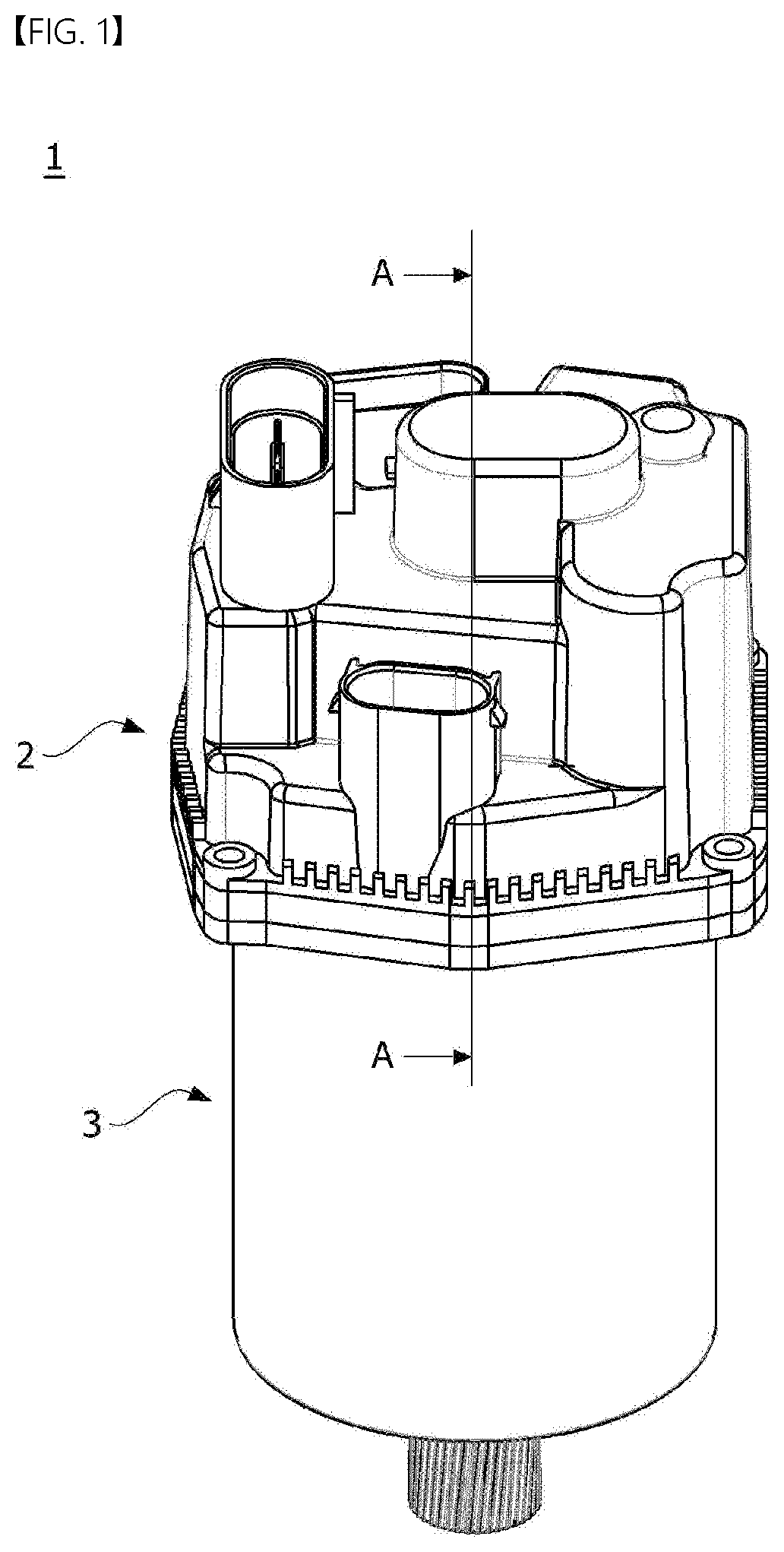
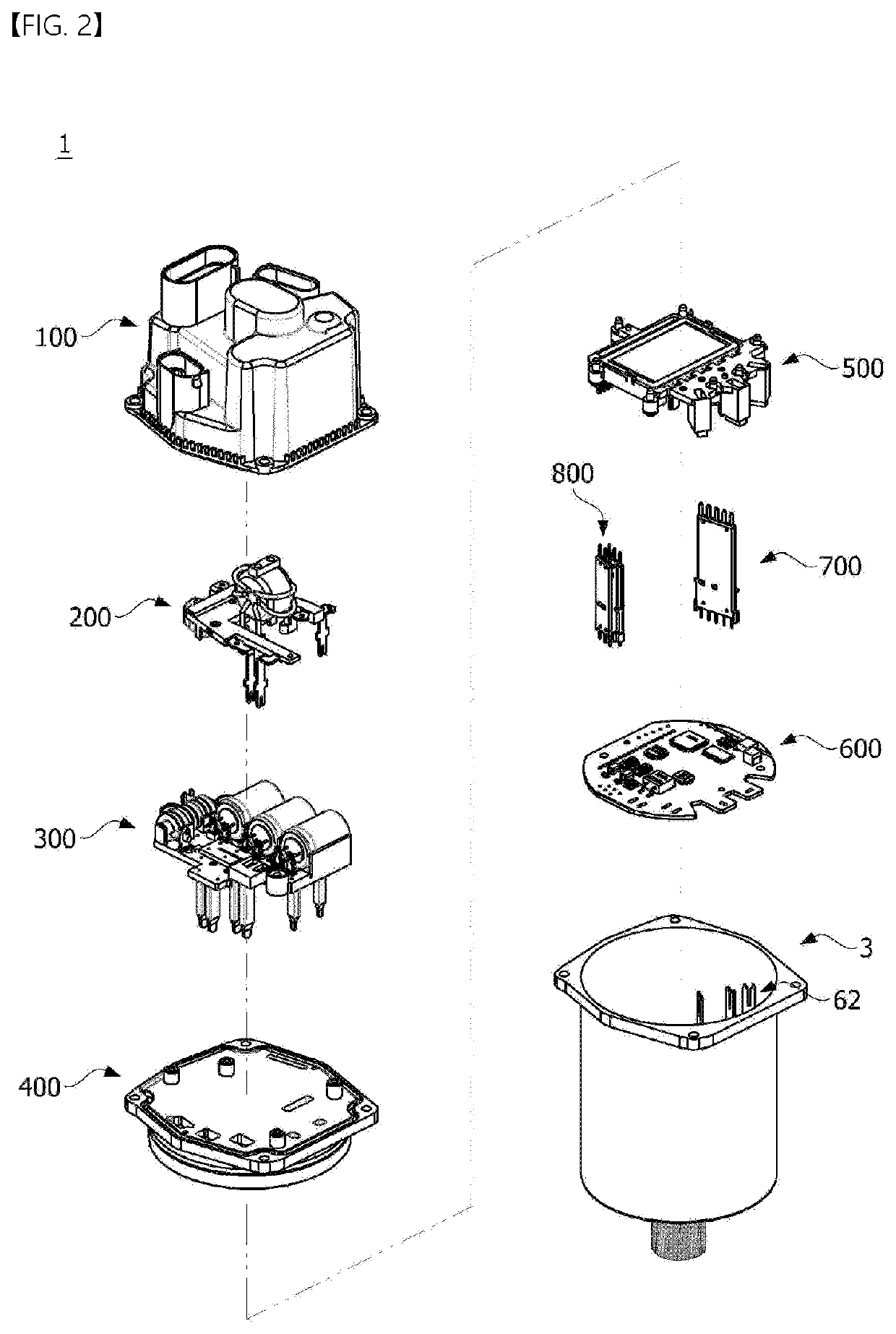
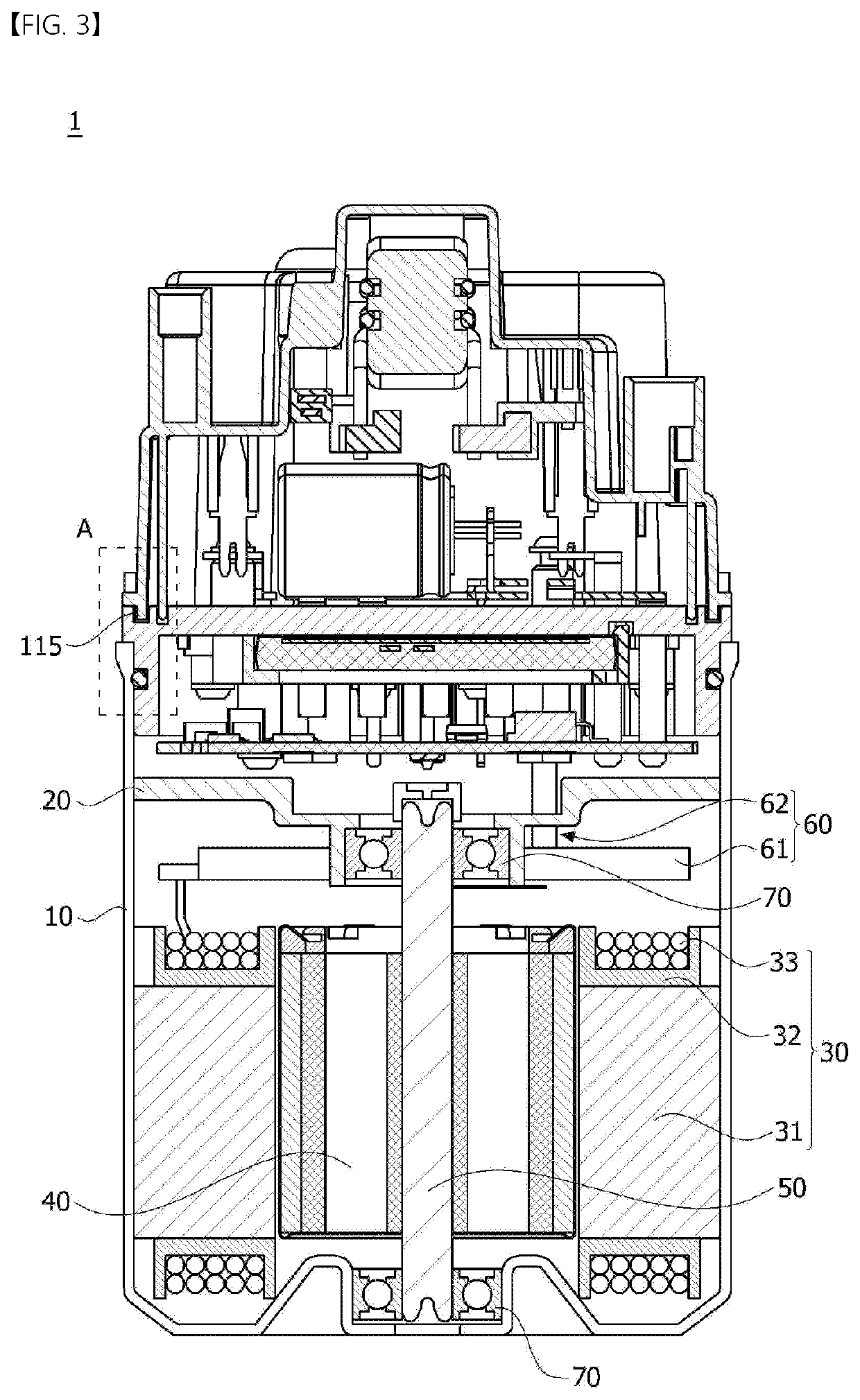
[0122]FIG. 2 is an exploded perspective view of the motor assembly according to the embodiment in which a power module unit is disposed, FIG. 3 is a cross-sectional view illustrating the motor assembly according to the embodiment, and FIG. 4 is a plan view of the motor assembly according to the embodiment. Here, FIG. 3 may be a cross-sectional view taken along line A-A in FIG. 1.

[0123]Referring to FIGS. 1 to 3, the controller 2 may include a controller housing 100, a common-mode (CM) filter unit 200, a differential-mode (DM) filter unit 300, a controller cover 400, a power module unit 500 according to the first embodiment, a substrate 600, and a connector unit. Here, the connector unit may include a first connector 700 and a second connector 800. Here, the controller housing 100 may be referred to as a first housing. In addition, the controller cover 400 may be referred to as a first cover unit.

[0124]The connector unit may pass through the controller cover 400. Here, the connector ...

second embodiment

[0318]FIG. 36 is an exploded perspective view illustrating the motor according to the embodiment in which the power module unit 500a is disposed.

[0319]Referring to FIGS. 1 and 36, the motor assembly 1 according to the embodiment may include the controller 2 and the motor 3. In addition, the controller 2 may include the controller housing 100, the CM filter unit 200, the DM filter unit 300, the controller cover 400, the power module unit 500a according to the second embodiment, the substrate 600, the first connector 700, and the second connector 800.

[0320]Hereinafter, in describing the motor assembly 1 according to the embodiment in which the power module unit 500a according to the second embodiment is disposed, the same components described in the motor assembly 1, in which the power module unit 500 according to the first embodiment is disposed, are described with the same reference numerals, and thus detailed descriptions of the controller housing 100, the CM filter unit 200, the ...


PUM


Abstract

An embodiment relates to a controller and a motor assembly comprising same, the controller comprising: a substrate; a controller housing disposed on the substrate; a CM filter unit disposed between the substrate and the controller housing; a DM filter unit disposed under the CM filter unit; a controller cover disposed between the substrate and the DM filter unit; a power module unit disposed between the substrate and the controller cover; and a connector unit coupled to the substrate, wherein the power module unit comprises a power module and a mold unit surrounding the power module. Accordingly, the heat generating problem of the power module unit can be resolved.

Description

CROSS REFERENCE TO RELATED APPLICATIONS[0001]This application is the National Phase of PCT International Application No. PCT / KR2018 / 008514, filed on Jul. 27, 2018, which claims priority under 35 U.S.C. 119(a) to Patent Application Nos. 10-2017-0128155, filed in the Republic of Korea on Sep. 29, 2017, 10-2017-0133853, filed in the Republic of Korea on Oct. 16, 2017, and 10-2017-0150611, filed in the Republic of Korea on Nov. 13, 2017, all of which are hereby expressly incorporated by reference into the present application.TECHNICAL FIELD[0002]An embodiment relates to a controller and a motor assembly including the same.BACKGROUND ART[0003]Motors are devices that convert electric energy into rotational energy using a force applied to a conductor in a magnetic field. Recently, with the expansion of the use of the motors, the role of the motor has become important. In particular, as vehicle electrification progresses rapidly, demands for the motor applied to a steering system, a braking...

Claims


Application Information

Patent Timeline
IPC IPC(8): H02K11/33H02K5/22H02K5/06H05K7/20
CPCH02K5/225H05K7/209H02K11/33H02K5/06H02K5/22H02K11/02H05K7/20854H05K2201/0999
Inventor KIM, CHAN SEOKSONG, KUN YONGSONG, DUCK HYUN
Owner LG INNOTEK CO LTD
Features
  • Generate Ideas
  • Intellectual Property
  • Life Sciences
  • Materials
  • Tech Scout
  • Unparalleled Data Quality
  • Higher Quality Content
  • 60% Fewer Hallucinations
Learn More