Wearable device

a wearable device and bracelet technology, applied in the field of wearable devices, can solve the problems of complicated structure, difficult use of buckles, and difficult placement of bracelets, and achieve the effect of convenient adjustment for different body parts and straightforward placemen

Active Publication Date: 2020-09-10
DNANUDGE LTD
View PDF0 Cites 1 Cited by
  • Summary
  • Abstract
  • Description
  • Claims
  • Application Information

AI Technical Summary

Benefits of technology

[0009]The present invention aims to provide a wrist-worn device which is straightforward to put on with one hand and easily adjustable for di

Problems solved by technology

However buckles can be difficult to employ in use because they require both hands to operate.
The bracelet diameter may be about the width of the user's palm, so bracelets can be difficult to put on but they stay loose on the wrist.
However they have a complicated structure and it is difficult to adjust the length of the buckles without using specialist tools.
However their elast

Method used


Image

  • Wearable device
  • Wearable device
  • Wearable device

Examples


first embodiment

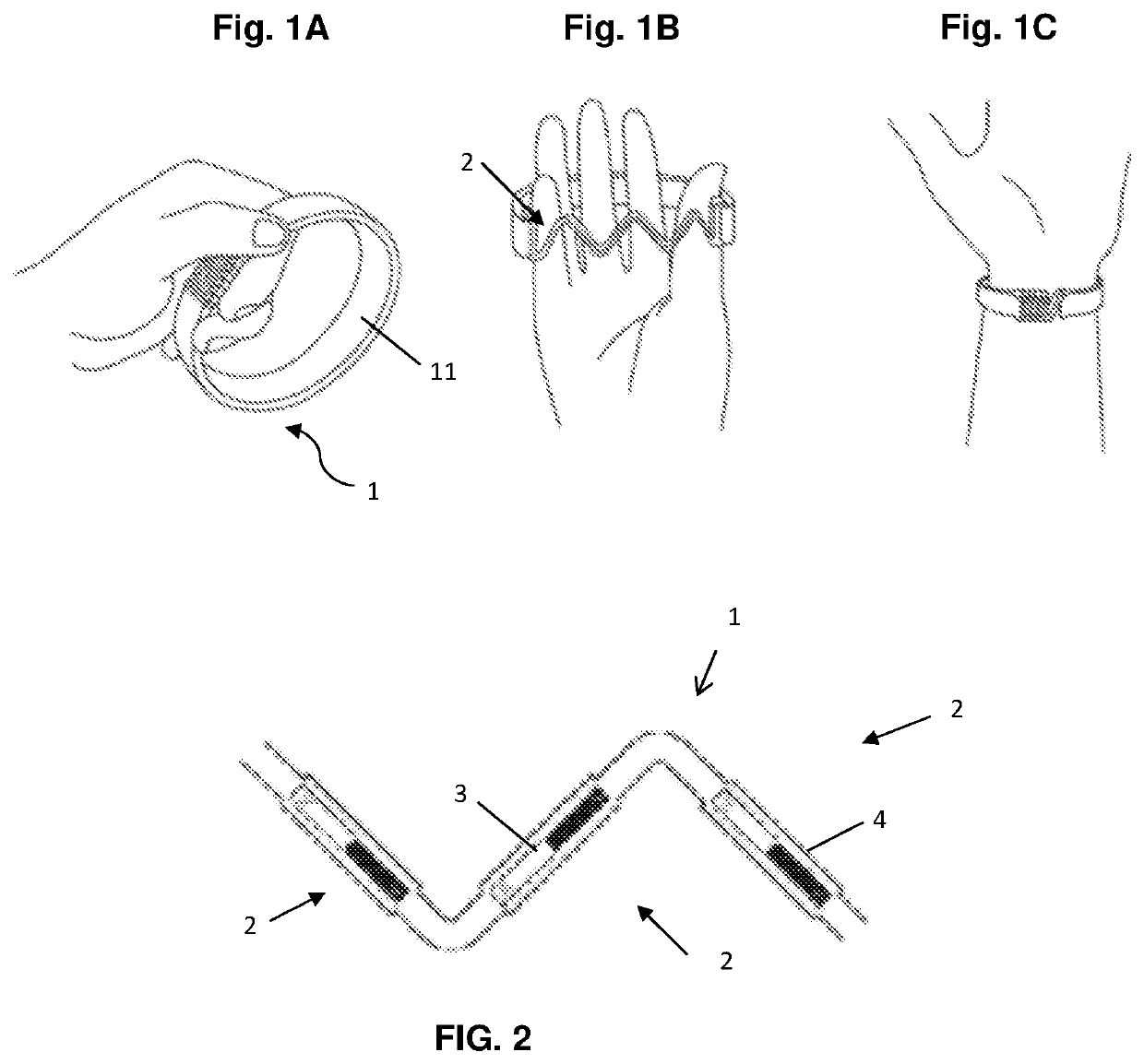
[0027]Referring firstly to FIG. 1, a wearable device 1 which is the invention is shown including a plurality of elongate links 2 that are connected pairwise to form a chain. The term “elongate” means that the links have a greater extent in one direction than another direction, for example they may be have an extent at least twice, at least 3 times, at least 5 times or even at least 8 times as long in one direction as in another transverse direction. For example, the links may be rectangular or substantially rod-like in shape. Each link may be substantially rigid.

[0028]Each link 2 has two ends, and each end is attached to a different corresponding neighbouring link. The attachment is preferably permanent (i.e. it is not broken in typical use of the wearable device) but allows neighbouring links to rotate relative to each other in at least two dimensions. The attachment between neighbouring links may, for example, be provided by a hinge or a pivot between rigid elements of the respect...

second embodiment

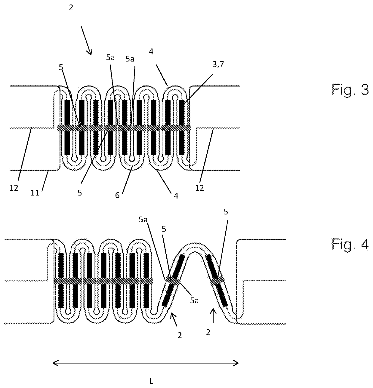
[0039]Note that in a variation of the second embodiment, the conductive elements 5 may be replaced with respective capacitive elements (which optionally are entirely within the cover 4). The corresponding capacitive elements of neighbouring links interact capacitatively with each other when the links are in the side-by-side arrangement. Thus, again, the impedance of the chain of links depends upon whether neighbouring links are side-by-side.

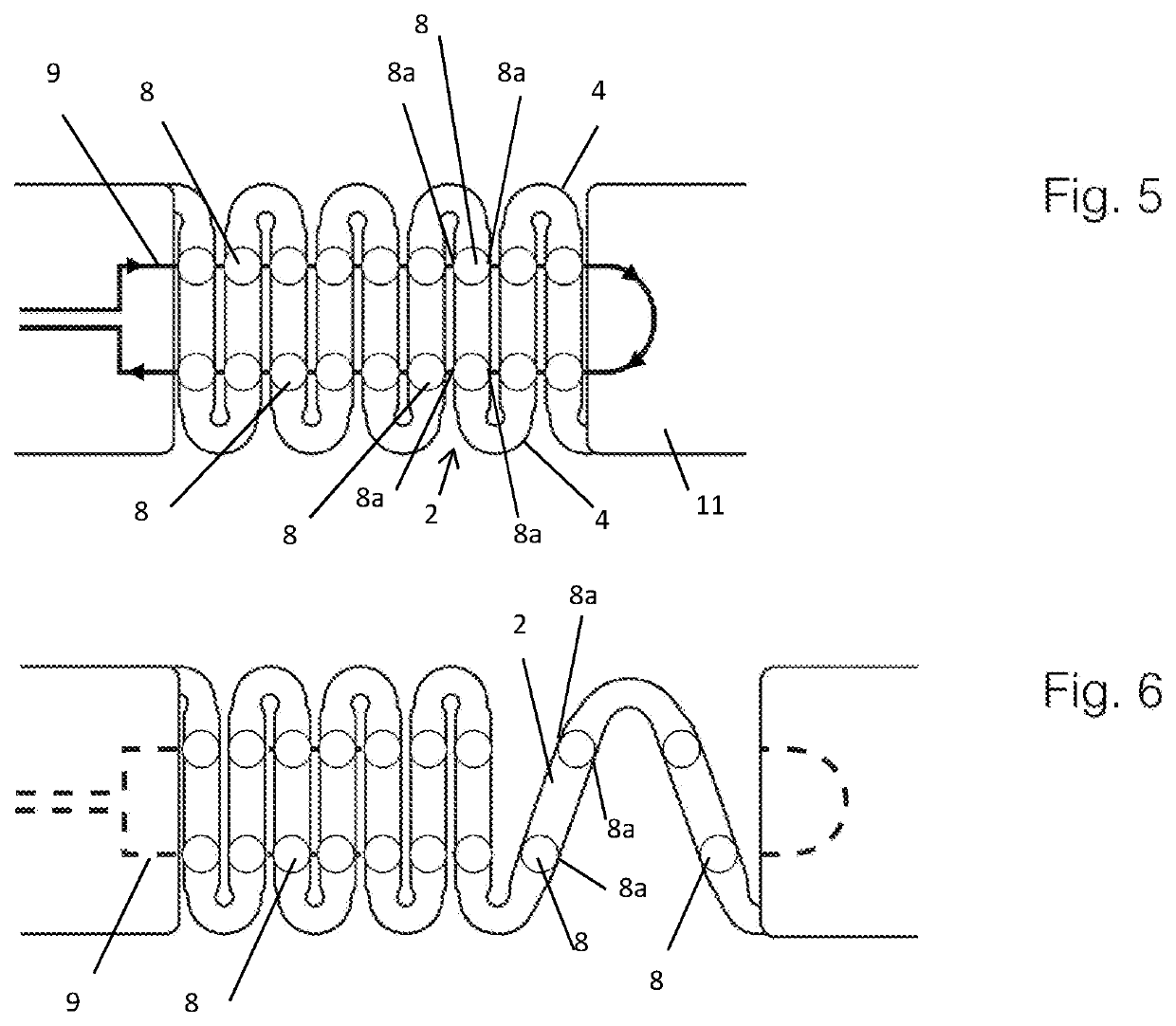
[0040]FIG. 5 shows a wearable device which is a third embodiment of the invention, with the links in a side-by-side arrangement. Again, elements having the same meaning as in the first embodiment are designated by the same reference numeral. As in the first embodiment each link 2 includes a magnetic element, but in FIG. 5 the magnetic elements are omitted for simplicity. The third embodiment of the invention has the same external appearance and manner of use as illustrated in FIG. 1. The side-by-side arrangement represents a state in which the we...


PUM


Abstract

A wrist-worn device having the form of a continuous loop. The device comprises a plurality of elongate links, each link comprising at least one magnet, the links being connected to form a chain with neighbouring links being pivotable with respect to one another about a pivot axis that is substantially radial with respect to said loop. The magnets of neighbouring links have a respective positioning and polarity to provide an attractive force between the pair of neighbouring links when the pair of neighbouring links are in a side-by-side arrangement, whereby the chain of links has a first configuration in which the links are retained by the attractive force in the side-by-side arrangement, and a second configuration of greater length than the first configuration.

Description

FIELD OF THE INVENTION[0001]The present invention relates to a wearable device.BACKGROUND OF THE INVENTION[0002]Wearable devices are devices that can be worn on the body as accessories. In the field of wearable devices, connection structures that secure a device to a user's body typically include a loop for encircling a part of the user's body, and the loop is either selectively openable or (permanently) closed using a connection structure.[0003]Openable connection structures connect two parts of a device that would typically not be connected when the device is not worn. An example of an open structure is where two ends of a strap are joined by a connecting buckle. Straps can be formed of flexible materials, such as leather, which are pleasant to wear for protracted periods. However buckles can be difficult to employ in use because they require both hands to operate.[0004]Closed connection structures form a (permanently) closed loop, but some permit the circumference of the loop to ...

Claims


Application Information

Patent Timeline
IPC IPC(8): A44C5/00A44C5/04A44C5/06A44C5/22
CPCA44D2203/00A61B5/681A44C5/22A44C5/04A44C5/0007A44C5/06A45F2005/008H01F7/0215A44C5/08A45F5/00
Inventor TOUMAZOU, CHRISTOFERSOHBATI, MOHAMMADREZAHU, KEREN
Owner DNANUDGE LTD
Why Eureka
Try Eureka