Continuous casting nozzle

a technology of continuous casting and nozzle, which is applied in the direction of casting apparatus, melt-holding vessels, manufacturing tools, etc., can solve the problems of insufficient exertion of inclusion adhesion reducing performance, degrading the quality of steel slab, and narrowing of inner holes and subsequent blockages, so as to improve the quality of steel and improve the thermal spalling resistance

Inactive Publication Date: 2020-09-10
AKECHI CERAMICS
View PDF0 Cites 2 Cited by
  • Summary
  • Abstract
  • Description
  • Claims
  • Application Information

AI Technical Summary

Benefits of technology

[0008]According to the continuous casting nozzle as claimed in claim 1, adhesion of inclusions in the molten steel to the portion in contact with the molten steel can be reduced even when the nozzle temperature is low, with the result that the nozzle hole can be prevented from being blocked and the continuous casting nozzle can contribute to an improvement in the quality of steel.
[0009]According to the continuous casting nozzle as claimed in claim 2, the continuous casting nozzle can be configured to have a higher thermal spalling resistance.
[0010]According to the continuous casting nozzle as claimed in claim 3, the aforementioned effect of claim 1 can be achieved more satisfactorily.
[0011]According to the continuous casting nozzle as claimed in claim 4, the aforementioned effect of claim 1 can be achieved more satisfactorily.
[0012]According to the continuous casting nozzle as claimed in claim 5, the aforementioned effect of claim 1 can be achieved more satisfactorily.
[0013]According to the continuous casting nozzle as claimed in claim 6, the aforementioned effect of claim 1 can be achieved more satisfactorily.

Problems solved by technology

In casting a steel slab, alumina inclusions in molten steel repeatedly adhere to, coalesce on and drop from an inner hole surface of a continuous casting nozzle to be taken into the steel slab together with the molten steel flow, resulting in a steel slab defect which degrades the quality of the steel slab.
Furthermore, the alumina inclusions may adhere to the inner hole surface of the continuous casting nozzle, causing narrowing of the inner hole and subsequent blockage.
However, this continuous casting nozzle has a problem that an inclusion adhesion reducing performance is not sufficiently exerted when a temperature of the nozzle decreases until molten steel flows through the nozzle hole from the time of completion of preheating.

Method used


Image

  • Continuous casting nozzle
  • Continuous casting nozzle
  • Continuous casting nozzle

Examples


embodiment 1

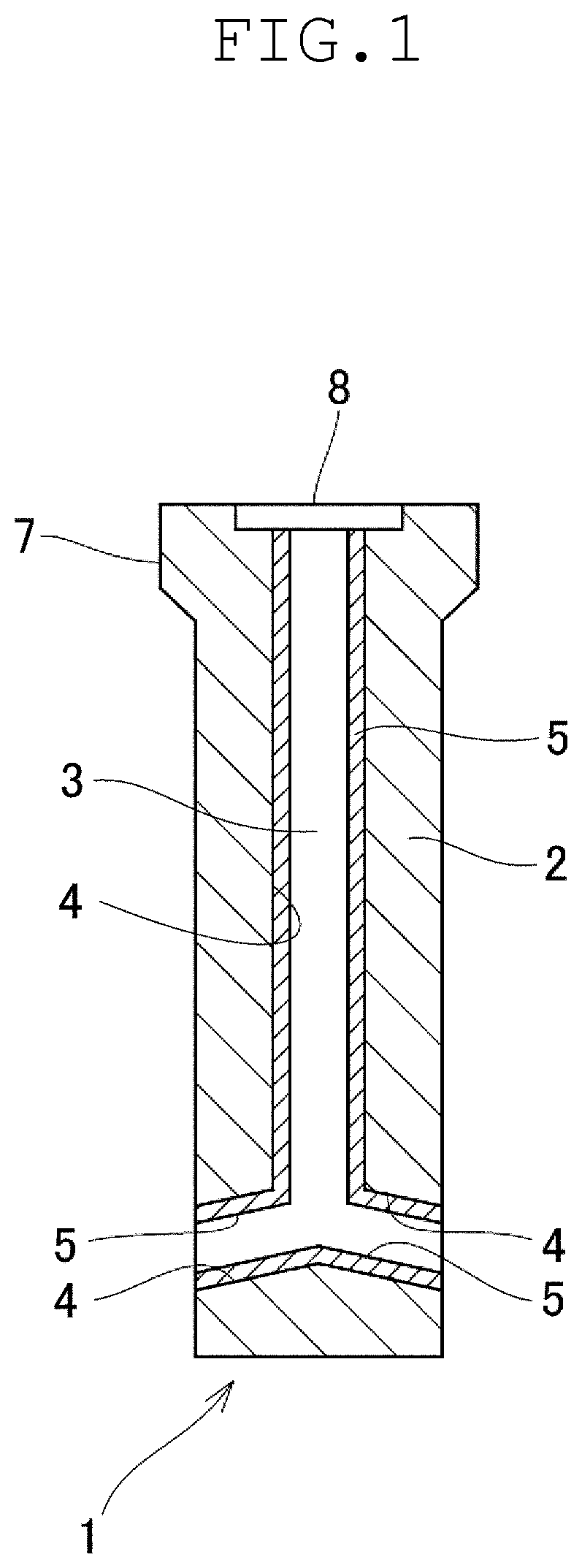
[0019]The continuous-casting nozzle in accordance with the present invention will be described with reference to an embodiment shown in the drawings. As shown in FIG. 11, a continuous casting nozzle 1 of this embodiment has a nozzle main body 2 and a nozzle hole 3 formed through the nozzle main body 2 for flowing molten steel. The nozzle hole 3 has an inner surface 4 on which an alumina-hardly-adherable refractory 5 containing components of MgO, CaO and SiO2 is disposed. The configuration of each component of the continuous casting nozzle 1 will be described in detail below.

[0020]The continuous casting nozzle 1 is an immersion nozzle which is disposed between a tundish and a mold and used when molten steel is poured from the tundish into the mold. The nozzle hole 3 through which the molten steel flows has a surface layer portion formed by the alumina-hardly-adherable refractory 5, whereas the nozzle main body 2 is made of a conventional alumina-black lead refractory.

[0021]The nozzle...


PUM

PropertyMeasurementUnit
thicknessaaaaaaaaaa
thicknessaaaaaaaaaa
thicknessaaaaaaaaaa

Abstract

A continuous casting nozzle 1 includes a nozzle main body 2 and a nozzle hole 3 formed to extend through the nozzle main body so that molten steel flows therethrough, and an alumina-hardly-adherable refractory 5 containing components of MgO, CaO and SiO2 is disposed on an inner surface defining the nozzle hole. Consequently, even when a temperature of the nozzle is low, adhesion of inclusions in molten steel to a portion in contact with the molten steel can be reduced, with the result that the nozzle hole can be prevented from being blocked and the continuous casting nozzle can contribute to an improvement in the steel quality.

Description

TECHNICAL FIELD[0001]The present invention relates to a continuous casting nozzle used for continuous casting, such as an immersion nozzle, a long nozzle and a tundish upper nozzle for injecting molten steel from a tundish into a mold. More specifically, the present invention relates to a continuous casting nozzle which can contribute to prevention of inclusion adhesion and improvement in the steel quality by arranging a material reacting with inclusions present in molten steel on an inner hole surface.BACKGROUND ART[0002]In casting a steel slab, alumina inclusions in molten steel repeatedly adhere to, coalesce on and drop from an inner hole surface of a continuous casting nozzle to be taken into the steel slab together with the molten steel flow, resulting in a steel slab defect which degrades the quality of the steel slab. Furthermore, the alumina inclusions may adhere to the inner hole surface of the continuous casting nozzle, causing narrowing of the inner hole and subsequent bl...

Claims


Application Information

Patent Timeline
Patent Type & Authority Applications(United States)
IPC IPC(8): B22D41/54B22D11/10
CPCB22D41/54B22D11/10C04B35/013C04B35/0435C04B35/06C04B35/20C04B35/22C04B35/66C04B2235/3206C04B2235/3208C04B2235/3418
Inventor SHINATO, MASAHIROKAWASE, MASANARI
Owner AKECHI CERAMICS
Why Eureka
Try Eureka