Ladle refining air brick with micro argon bubbles formed through bottom blowing

A technology of ladle refining and air-permeable bricks, applied in the field of air-permeable bricks, can solve the problems that core components are easily eroded by molten steel, it is difficult to take into account the long service life, and uniform argon bubbles cannot be obtained, so as to save the cost of argon blowing and improve casting. sex, good use effect

Active Publication Date: 2016-08-17
WUHAN UNIV OF SCI & TECH
View PDF7 Cites 0 Cited by
  • Summary
  • Abstract
  • Description
  • Claims
  • Application Information

AI Technical Summary

Problems solved by technology

[0004] Existing gas permeable bricks for ladle argon blowing and refining often have thermal stress concentration at the end of the permeable brick slit, which leads to cracks and makes the whole permeable brick scrap
Or the structure is complex, not easy to repair and replace
[0005] "A kind of arc-shaped slit breathable brick" (CN203295550U) patent technology, by adopting the arc-shaped slit structure with radiation distribution, the thermal stress cracking phenomenon at the end of the slit is avoided, but uniform argon bubbles cannot be obtained, and the size of the argon bubbles Uncontrollable, not conducive to the use of fine argon bubble technology to refine molten steel
[0006] "Breathable Brick" (CN204174227U) patented technology, although a large and uniform bubble group is obtained, but the structure is very complicated, the core components are easily eroded by molten steel, and the service life is affected, and because of the complex structure, it is inconvenient to replace, if the whole Replacement also requires downtime and creates waste
[0007] The currently used gas permeable bricks for argon blowing and refining of ladles are difficult to balance the long service life and the effect of obtaining evenly distributed argon bubble groups

Method used


Image

  • Ladle refining air brick with micro argon bubbles formed through bottom blowing
  • Ladle refining air brick with micro argon bubbles formed through bottom blowing
  • Ladle refining air brick with micro argon bubbles formed through bottom blowing

Examples


Embodiment 1

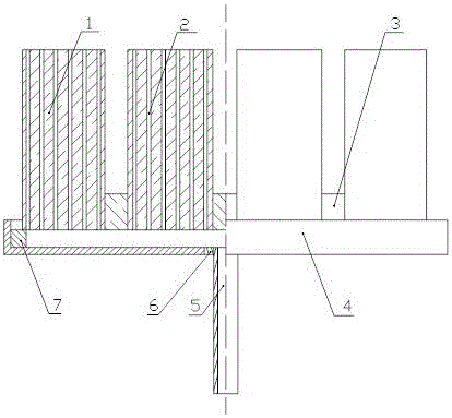
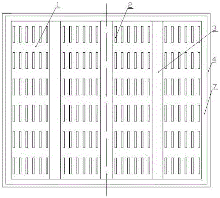
[0027] A gas permeable brick with bottom-blown fine argon bubbles for ladle refining. The breathable bricks are as figure 1 and figure 2 As shown, including refractory brick 1, base 4 and air supply pipe 5. The base 4 is as figure 1 , figure 2 , Figure 4 and Figure 5 As shown, a rectangular frame is fixed on the periphery of the rectangular bottom plate, and a strip-shaped boss 7 is arranged close to the inner wall of the rectangular frame. The strip-shaped boss 7 is located on the upper plane of the rectangular bottom plate, and the height of the strip-shaped boss 7 The height ratio to the rectangular frame is 1: (2~3). Such as figure 1 As shown, there are refractory bricks 1 built on the strip boss 7, and there are 4 refractory bricks 1, and refractory mud 3 is bonded between each refractory brick. Such as figure 2 As shown, each refractory brick 1 is provided with a ventilation slit 2. Such as figure 1 , Figure 4 and Figure 5 As shown, a sleeve 6 is fixe...

Embodiment 2

[0031] A gas permeable brick with bottom-blown fine argon bubbles for ladle refining. The breathable bricks are as figure 1 and figure 2 As shown, including refractory brick 1, base 4 and air supply pipe 5. The base 4 is as figure 1 , figure 2 , Figure 4 and Figure 5 As shown, a rectangular frame is fixed on the periphery of the rectangular bottom plate, and a strip-shaped boss 7 is arranged close to the inner wall of the rectangular frame. The strip-shaped boss 7 is located on the upper plane of the rectangular bottom plate, and the height of the strip-shaped boss 7 The height ratio to the rectangular frame is 1: (2~3). Such as figure 1 As shown, there are refractory bricks 1 built on the strip-shaped boss 7, and the number of refractory bricks 1 is 2 to 3 or 5 to 8, and refractory mud 3 is bonded between each refractory brick. Such as figure 2 As shown, each refractory brick 1 is provided with a ventilation slit 2. Such as figure 1 , Figure 4 and Figure 5...

Embodiment 3

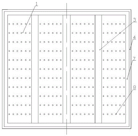
[0035] A gas permeable brick with bottom-blown fine argon bubbles for ladle refining. The breathable bricks are as figure 1 and image 3 As shown, including refractory brick 1, base 4 and air supply pipe 5. The base 4 is as figure 1 , image 3 , Figure 4 and Figure 5 As shown, a rectangular frame is fixed on the periphery of the rectangular bottom plate, and a strip-shaped boss 7 is arranged close to the inner wall of the rectangular frame. The strip-shaped boss 7 is located on the upper plane of the rectangular bottom plate, and the height of the strip-shaped boss 7 The height ratio to the rectangular frame is 1: (2~3). Such as figure 1 As shown, there are refractory bricks 1 built on the strip boss 7, and there are 4 refractory bricks 1, and refractory mud 3 is bonded between each refractory brick. Such as image 3 As shown, each refractory brick 1 is provided with ventilation holes 8 . Such as figure 1 , Figure 4 and Figure 5 As shown, a sleeve 6 is fixed a...


PUM

PropertyMeasurementUnit
Center distanceaaaaaaaaaa

Abstract

The invention relates to a ladle refining air brick with micro argon bubbles formed through bottom blowing. According to the technical scheme, a strip-shaped boss (7) is fixed to the inner wall of a rectangular framework in a closely attached mode, 2-8 refractory bricks (1) are built on the strip-shaped boss (7), the refractory bricks (1) are bonded with refractory mortar (3), and the refractory bricks (1) are provided with air slits (2) or air holes (8) serving as independence channels; an air supply pipe (5) is concentrically fixed in a sleeve (6) fixed to the center of a base (4); for the air slits (2), the width is 0.15-0.20 mm, the length is 2-100 times the width, the center distance is 25-50 mm, and the area ratio of the slit area to the upper surfaces of the refractory bricks (1) is 1:(125-300); for the air holes (8), the diameter is 0.15-0.20 mm, the center distance is 25-50 mm, and the area ratio of the hole area to the upper surfaces of the refractory bricks (1) is 1:(200-500). The ladle refining air brick with micro argon bubbles formed through bottom blowing has the advantages of being convenient to install and maintain, good in use effect and long in service life.

Description

technical field [0001] The invention belongs to the technical field of air-permeable bricks used for ladle refining. In particular, it relates to a breathable brick for bottom-blown fine argon bubbles used in ladle refining. Background technique [0002] The content of non-metallic inclusions in cast products (continuous casting semi-finished products or large steel ingots) has a significant impact on the quality of steel. Therefore, the main task of iron and steel enterprises is to produce the final product with the lowest possible content of non-metallic inclusions (aluminosilicate, calcium aluminate, and other complex non-metallic inclusions), so as to produce Products with increasing requirements for cracking are used in shipbuilding, deep-water operation metal platforms, bridge construction, aerial work metal platforms, oil and gas pipelines and other fields. [0003] Studies have shown that blowing argon into molten steel can play a role in refining molten steel: it ...

Claims


Application Information

Patent Timeline
IPC IPC(8): C21C7/072B22D41/02
CPCB22D41/02C21C7/072
Inventor 吴开明伊萨也夫·奥列格特罗参·阿纳托里·伊万诺维奇欧莱格山德·格热斯胡丞杨
Owner WUHAN UNIV OF SCI & TECH
Why Eureka
Try Eureka