Method for ultrasonic welding

Active Publication Date: 2020-09-10
AUTO KABEL MANAGEMENTGMBH
View PDF0 Cites 0 Cited by
  • Summary
  • Abstract
  • Description
  • Claims
  • Application Information

AI Technical Summary

Benefits of technology

The patent proposes a way to prevent damage to the surface of a flat part during welded joints in motor vehicles. This is achieved by using a damping element that restricts the movement of the fastening element relative to the flat part and / or the joining part. This results in an optimal welded joint that is stable and durable over the entire life of the vehicle. The damping element is preferably placed on the fastening element to maximize its effectiveness in preventing damage.

Problems solved by technology

A problem with ultrasonic welding, however, is if movable parts are arranged in the vicinity of the weld point.
While the parts to be welded between the sonotrode and the anvil are secured through the force of the sonotrode directed vertically onto these, nevertheless other movable parts located in the vicinity of the weld point are unintentionally placed in motion by the mechanical oscillations during the welding process.
The movements induced can be translational movements, rotational movements or oscillatory movements, all of which reduce the quality of the welded connection and can lead to surface damage or even the formation of cracks.
The object cannot be achieved simply by holding down the movable parts, because in this case undesired marks and scratches may be created on the movable parts and also on the flat part and the bearing surface.
In this connection, coated parts, such as those with a tinned surface for corrosion protection, are particularly vulnerable to surface damage.

Method used


Image

  • Method for ultrasonic welding
  • Method for ultrasonic welding
  • Method for ultrasonic welding

Examples


Embodiment Construction

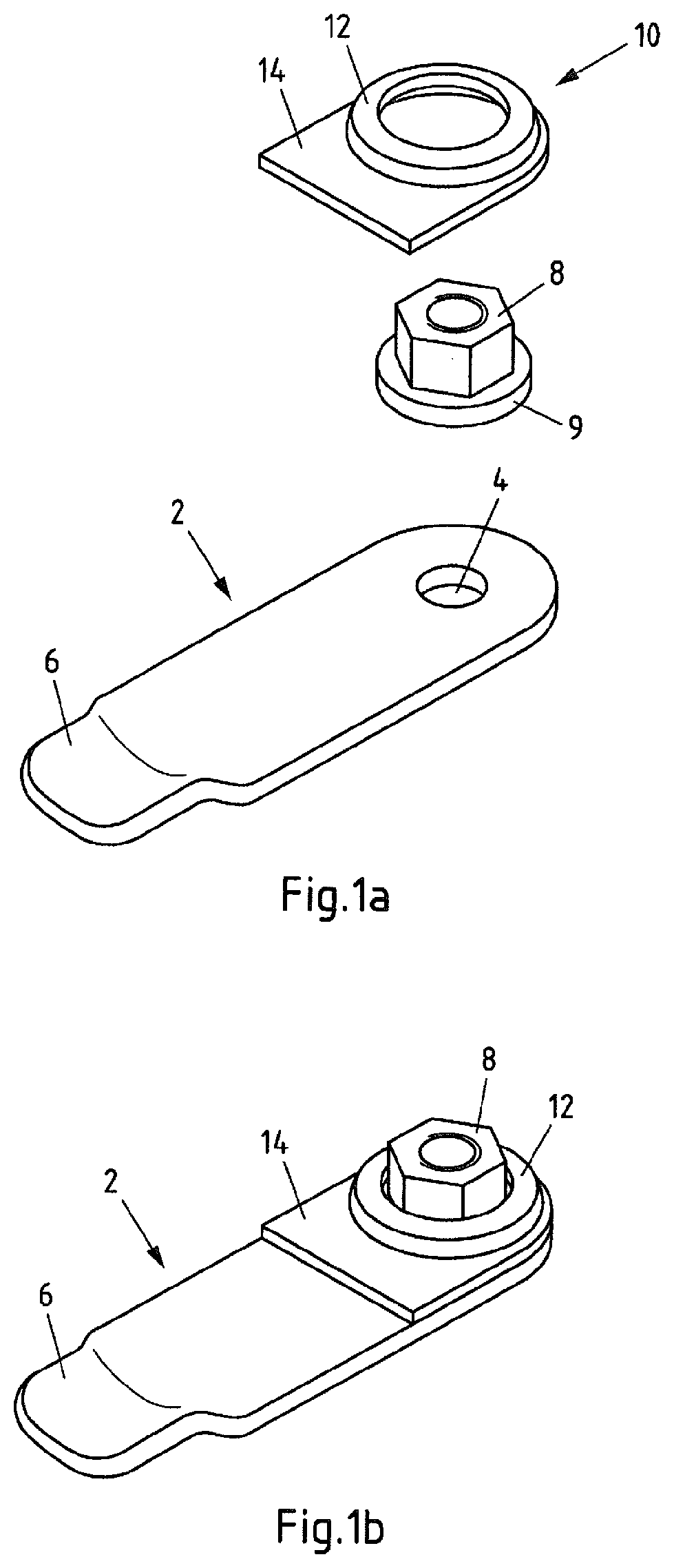
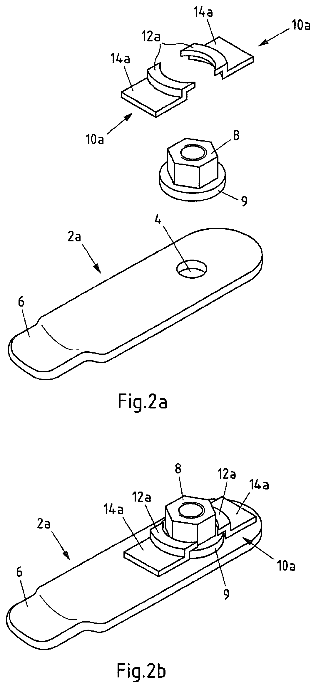
[0010]In an ultrasonic welding device, the weld metal to be welded can be arranged between the sonotrode and the anvil. In this case a flat part is welded to a joining part or connection part, by way of example a cable core, particularly strands of a cable, by means of ultrasonic welding (USW).

[0011]With USW oscillations are introduced into the flat part. These oscillations are able to spread across the flat part and are particularly transmitted to the components arranged on the flat part, particularly fasteners. These parts that are not secured to the flat part similarly start to oscillate and can cause damage to the surfaces of the parts through the vibrations thereby caused.

[0012]A fastening element can also be arranged on a flat part and particularly held between the flat part and a joining part in a positively locking manner. The fastening element, however, can also be arranged captively on the flat part without the joining part, e.g. by suitable pressing or similar. A damping ...


PUM

PropertyMeasurementUnit
Pressureaaaaaaaaaa
Pressureaaaaaaaaaa
Areaaaaaaaaaaa

Abstract

Ultrasonic welding device having a sonotrode (28) and an anvil (26), in which a flat part and at least one joining part are arranged between the sonotrode (28) and the anvil (26) during ultrasonic welding, and wherein a fastening element is held in a positively locking manner between the flat part and the joining part, and a damping element (22) that presses on the fastening element (8a) is provided, which is pressed on the fastening element in such a way that a relative movement between the fastening element and the flat part and / or the joining part is restricted during ultrasonic welding

Description

CROSS-REFERENCE TO RELATED APPLICATIONS[0001]This application is a divisional of U.S. application Ser. No. 15 / 548,987, which is the national phase entry of international patent application no. PCT / EP2016 / 050097 filed Jan. 6, 2016, the disclosures of which are incorporated herein by reference in their entirety. These applications all claim the benefit of German patent applications No. 10 2015 106 265.8, filed Apr. 23, 2015 and No. 20 2015 000 879.8, filed Feb. 6, 2015TECHNICAL FIELD[0002]The subject matter relates to an ultrasonic welding device and a method for ultrasonic welding.BACKGROUND ART[0003]Nowadays various welding methods are available which essentially differ simply by the way in which the heat is generated. The ultrasonic welding method has established itself as a tried and tested technique for strong and reliable connection of cables, clamps and fasteners particularly in motor vehicles.[0004]In ultrasonic welding, the electrical oscillations produced by an ultrasonic ge...

Claims


Application Information

Patent Timeline
IPC IPC(8): B23K20/26H01R4/02B23K20/10B23K20/24H01R43/02
CPCH01R4/027B23K20/106B23K20/24B23K2101/38B23K20/26B23K20/10H01R11/26H01R43/0263
Inventor BRUNNER, NICOLASZUSCHLAG, DANY
Owner AUTO KABEL MANAGEMENTGMBH
Why Eureka
Try Eureka