
Fast phase frequency detector

Active Publication Date: 2020-09-17
MONTAGE TECHNOLOGY CO LTD
View PDF0 Cites 0 Cited by
  • Summary
  • Abstract
  • Description
  • Claims
  • Application Information

AI Technical Summary

Benefits of technology

The patent text describes a new device that can quickly detect the frequency of a certain signal. This device uses special components that allow it to measure the signal quickly and accurately. This new device could help improve the speed and efficiency of electronic circuits.

Problems solved by technology

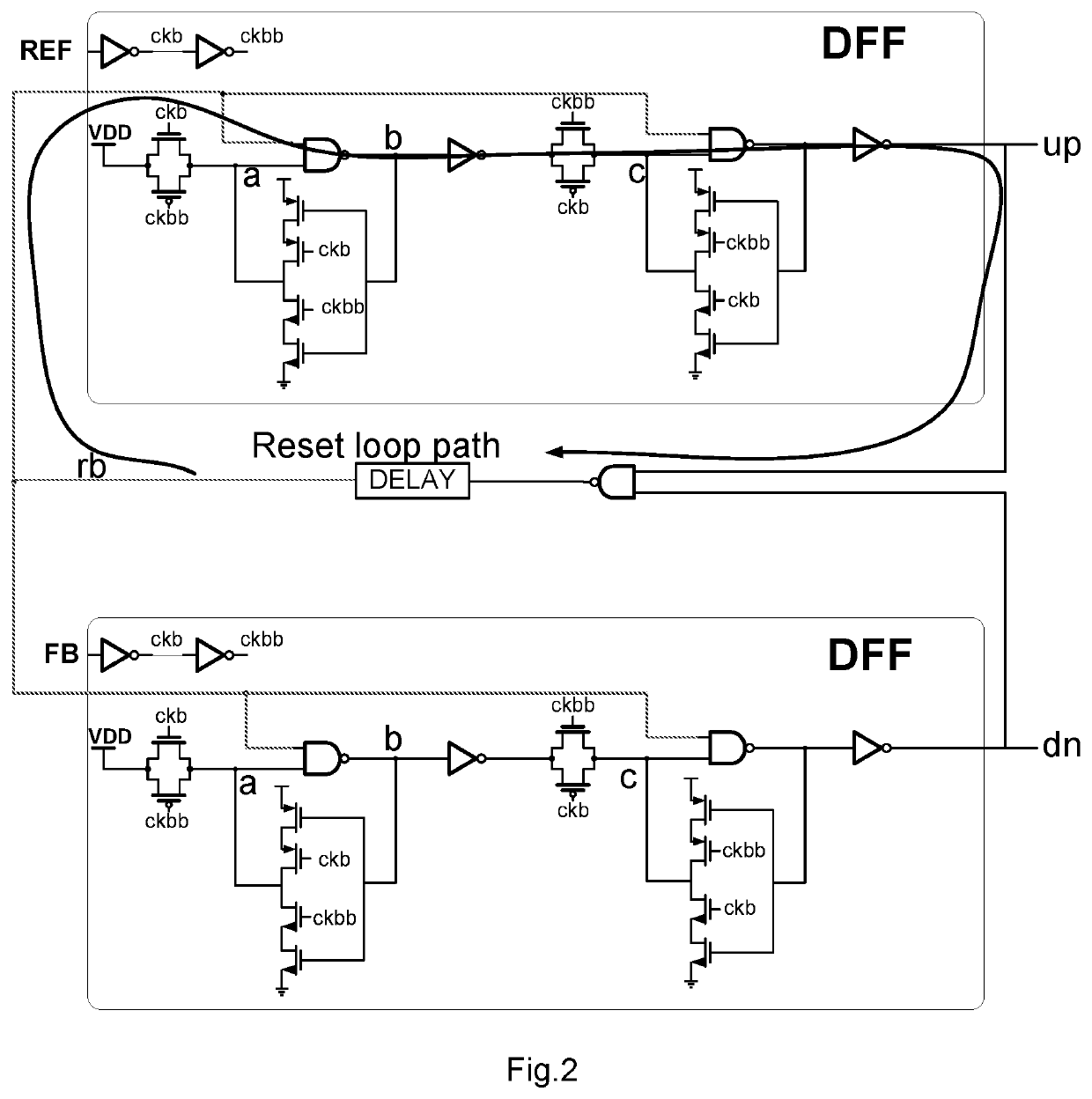
Due to the use of D flip-flops, the conventional phase frequency detector has a large reset loop delay, which limits the maximum operating frequency of the PFD.

Method used


Image

  • Fast phase frequency detector
  • Fast phase frequency detector
  • Fast phase frequency detector

Examples


Embodiment Construction

[0020]In the following description, many technical details are provided for readers to better understand the present application. However, it is understood by those ordinary skilled in the art that technical solutions claimed to be protected by those claims of the present application can also be realized even without these technical details and not based on various changes and modifications of the following embodiments.

[0021]In order to make the purpose, technical solutions and merits of the present application more clear, the embodiments of the present application will be further described in detail below with reference to the accompanying drawings.

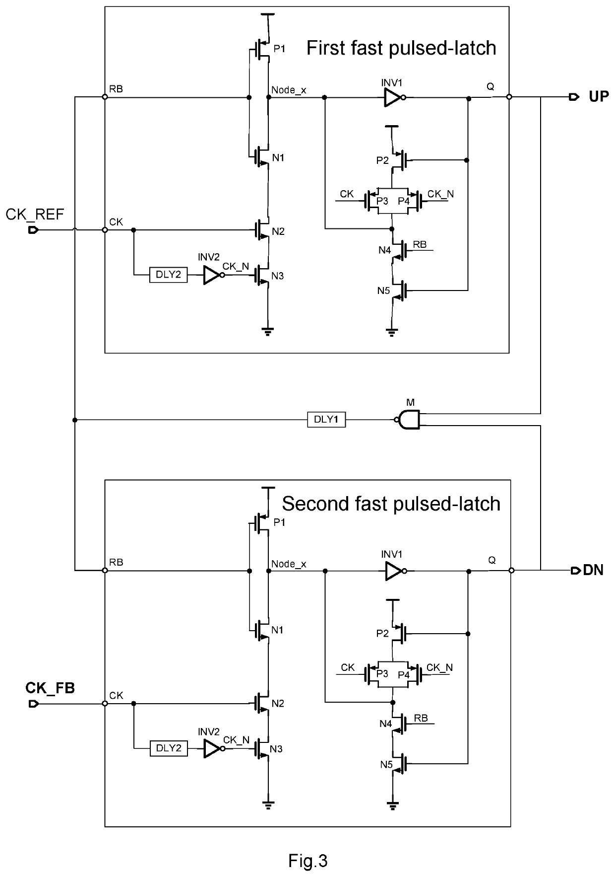
[0022]An embodiment of the present application relates to a fast phase frequency detector. FIG. 3 is a circuit diagram of the fast phase frequency detector.

[0023]Specifically, as shown in FIG. 3, the fast phase frequency detector comprises:

[0024]a first fast pulsed-latch, a second fast pulsed-latch, a NAND gate M and a first delay circui...


PUM


Abstract

Disclosed a fast phase frequency detector, comprising: two fast pulsed-latches, a NAND gate and an adjustable delay circuit. The fast pulsed-latches comprises: a pulse generating circuit, a reset circuit, and an output latch circuit; the pulse generating circuit is configured to generate a power supply pulse signal when a rising edge of the clock signal arrives, the power supply pulse signal causing the input of the output latch circuit to be a low level; the output latch circuit is configured to maintain its current output state when the clock signal or the reset signal is invalid; the reset circuit is configured to set the input of the output latch circuit to be a high level. By using fast pulsed-latches with clock and reset control, the fast phase frequency detector of the present application shortens the reset loop delay and increases the maximum operating frequency of the phase frequency detector.

Description

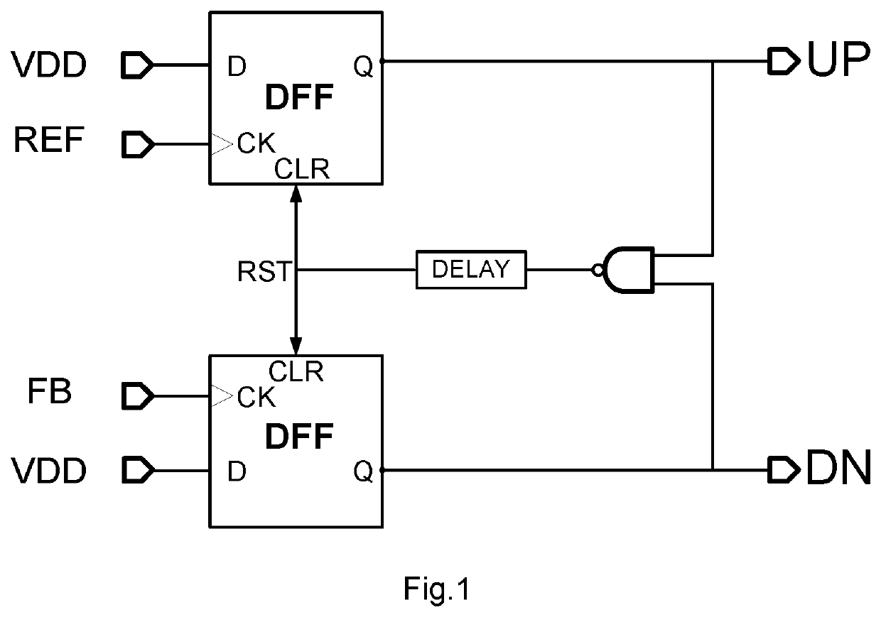
FIELD OF THE INVENTION[0001]The application relates to the field of integrated circuit design, and particularly relates to a fast phase frequency detector.BACKGROUND OF THE INVENTION[0002]As shown in FIG. 1, the main components of a conventional phase frequency detector (PFD) comprise: two D flip-flops (DFFs), a NAND gate, and a delay circuit. The two D flip-flops are driven by a reference clock signal (REF) and a feedback clock signal (FB), respectively. In normal operation, a reset signal (RST) of the D flip-flops is at a high level (i.e., logic high). When the later one of rising edges of the REF and the FB comes, both an up signal (UP) and a down signal (DN) output by the D flip-flops become high level, and the RST becomes low level (i.e., logic low). Then both the D flip-flops are reset simultaneously, both the UP and the DN become low level, and the RST is reset to high level. During the process, the delay for the reset signal RST to change from high level to low level and the...

Claims


Application Information

Patent Timeline
IPC IPC(8): H03L7/085
CPCH03L7/085H03D13/00H03D13/003H03L7/089
Inventor ZHANG, PENGZHANCHANG, ZHONGYUANLI, YANHONG
Owner MONTAGE TECHNOLOGY CO LTD
Learn More