
Digital phase-locked loop with reduced loop delay

a phase lock and loop technology, applied in the direction of electrical equipment, automatic control, etc., can solve the problems of reduced performance of all digital pll, unavoidable loop delay of components, and sensitive analog circuits to voltage, temperature and temperature variations, etc., to reduce loop delay and reduce delay

Inactive Publication Date: 2011-06-09
SAMSUNG ELECTRO MECHANICS CO LTD +1
View PDF6 Cites 10 Cited by
  • Summary
  • Abstract
  • Description
  • Claims
  • Application Information

AI Technical Summary

Benefits of technology

[0050]Hereinafter, the operation and effects of the invention will be described in detail with reference to the accompanying drawings.
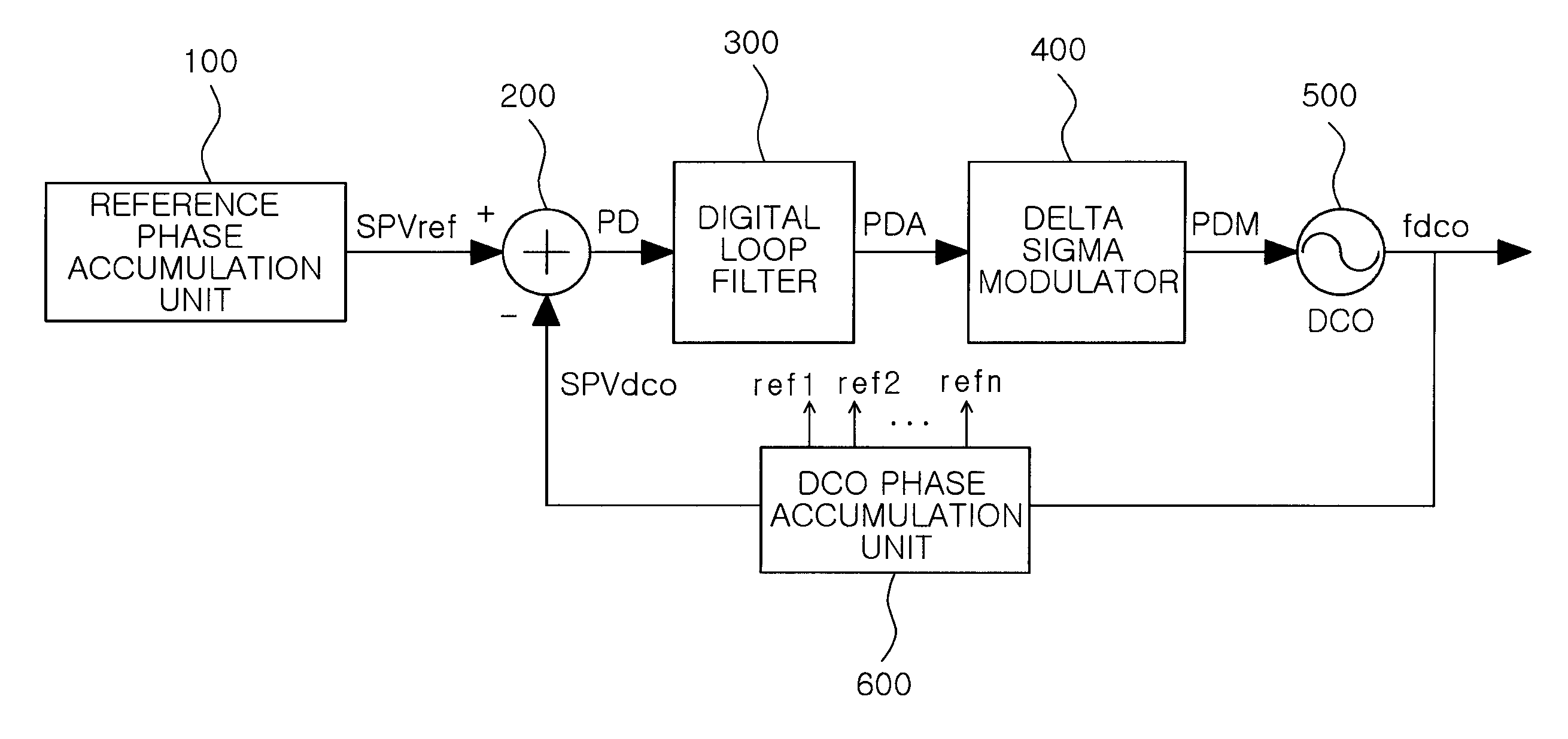
[0051]A digital phase-locked loop according to an exemplary embodiment of the invention will be described with reference to FIGS. 3 through 7. In FIG. 3, the reference phase accumulation unit 100 of the digital phase-locked loop according to this embodiment accumulates a predetermined division value according to a reference clock and samples the predetermined division value being accumulated to thereby output the reference sampling phase value SPVref to the phase detection unit 200.
[0052]The phase detection unit 200 detects the phase difference signal corresponding to a difference value between the reference sampling phase value SPVref from the reference phase accumulation unit 100 and the DCO sampling phase value SPVdco.
[0053]The digital loop filter 300 filters the phase difference signal PD from the phase detection unit 200 to thereby output an averaged phase difference signal to the digitally controlled oscillator 500.
[0054]The digitally controlled oscillator 500 generates the oscillation signal fdco having a predetermined frequency on the basis of the phase difference signal PDA averaged by the digital loop filter 300.
[0055]The DCO phase accumulation unit 600 accumulates a predetermined reference value according to the oscillation signal fdco from the digitally controlled oscillator 500 and samples the predetermined reference value being accumulated to thereby output the DCO sampling phase value SPVdco.

Problems solved by technology

However, these analog circuits are sensitive to process, voltage, and temperature (PVT) variations, which need to be considered when designing phase-locked loops.
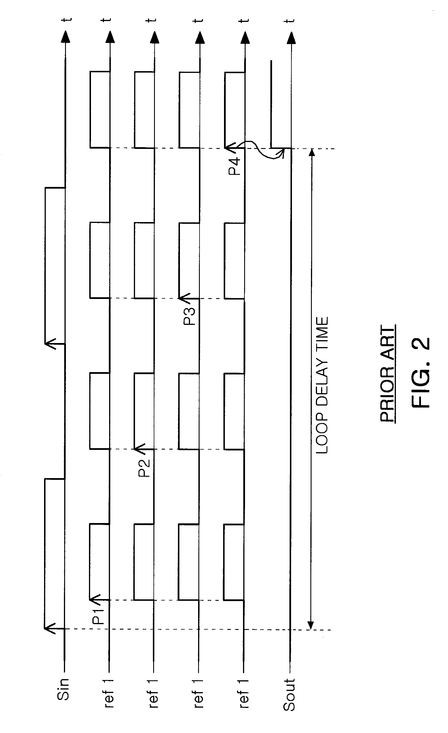
Therefore, the components thereof unavoidably have loop delay.
However, one report says that the performance of the all digital PLL may be reduced due to this phase delay in terms of phase noise and stability.

Method used


Image

  • Digital phase-locked loop with reduced loop delay
  • Digital phase-locked loop with reduced loop delay
  • Digital phase-locked loop with reduced loop delay

Examples


Embodiment Construction

[0033]Exemplary embodiments of the present invention will now be described in detail with reference to the accompanying drawings.

[0034]The invention may, however, be embodied in many different forms and should not be construed as being limited to the embodiments set forth herein. Rather, these embodiments are provided so that this disclosure will be thorough and complete, and will fully convey the scope of the invention to those skilled in the art. In the drawings, the shapes and dimensions may be exaggerated for clarity, and the same reference numerals will be used throughout to designate the same or like components.

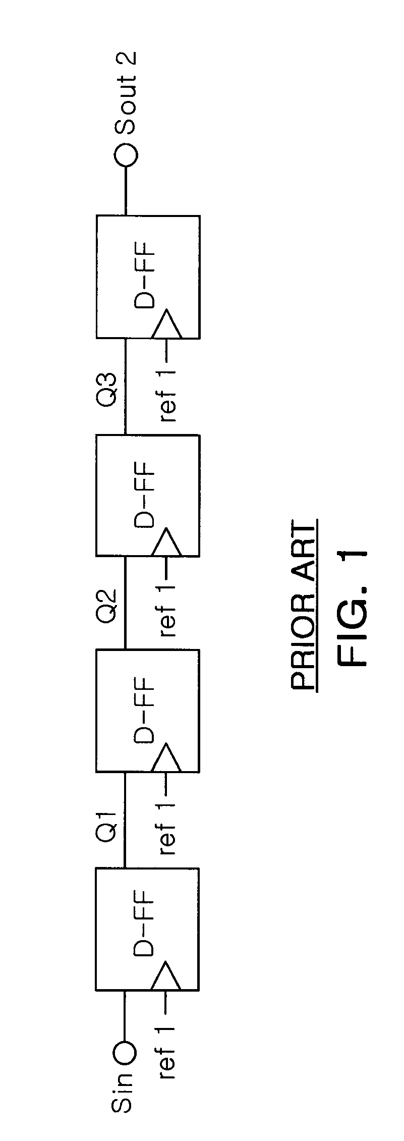
[0035]FIG. 3 is a block diagram illustrating a digital phase-locked loop according to an exemplary embodiment of the invention. FIG. 4 is a view illustrating the operation of an accumulator of a DCO phase accumulation unit according to an exemplary embodiment of the invention. FIG. 5 is a block diagram illustrating a D-FF circuit of a digital phase-locked loop according...


PUM


Abstract

There is provided a digital phase-locked loop. A digital phase-locked loop according to an aspect of the invention may include: a reference phase accumulation unit outputting a reference sampling phase value; a phase detection unit detecting a phase difference signal; a digital loop filter filtering and averaging the phase difference signal from the phase detection unit; a digitally controlled oscillator generating an oscillation signal having a predetermined frequency; a DOC phase accumulation unit outputting the DCO sampling phase value, and generating a plurality of first to n-th D-FFs having the same frequency and different phases delayed in a sequential manner; and first to n-th D-FFs included in a closed loop including the phase detection unit, the digital loop filter, the digitally controlled oscillator, and the DOC phase accumulation unit, and operating according to the plurality of first to n-th clock signals from the DCO phase accumulation unit, respectively.

Description

CROSS-REFERENCE TO RELATED APPLICATIONS[0001]This application claims the priority of Korean Patent Application No. 10-2009-0119924 filed on Dec. 4, 2009, in the Korean Intellectual Property Office, the disclosure of which is incorporated herein by reference.BACKGROUND OF THE INVENTION[0002]1. Field of the Invention[0003]The present invention relates to a digital phase locked loop that can be applied to a wireless communications system, and more particularly, to a digital phase locked loop with reduced loop delay that can reduce delay in a closed loop of a digital phase-locked loop by using multi-phase signals having phases and higher frequency than a reference signal.[0004]2. Description of the Related Art[0005]In general, an A / D converter, a clock generator producing clocks for a microprocessor, or a frequency synthesizer, which is the core component of a wireless communications system, is manufactured on the basis of a phase locked loop.[0006]Typically, phase-locked loops have bee...

Claims


Application Information

Patent Timeline
Patent Type & Authority Applications(United States)
IPC IPC(8): H03L7/08
CPCH03L7/1806H03L2207/50H03L7/099H03L7/07
Inventor KIM, GYU SUCKCHO, SEONG HWANSON, WOO KON
Owner SAMSUNG ELECTRO MECHANICS CO LTD
Learn More