Molding apparatus

Inactive Publication Date: 2020-09-24
FUJIFILM BUSINESS INNOVATION CORP
View PDF0 Cites 3 Cited by
  • Summary
  • Abstract
  • Description
  • Claims
  • Application Information

AI Technical Summary

Benefits of technology

The present disclosure is about a way to make sure that the strength of a material made from a bundle of continuous fibers doesn't decrease when it is molded using a resin. The technical effect of this invention is to maintain the strength of the material, compared to a different configuration where the fibers are twisted and resin is added.

Problems solved by technology

However, aspects of the non-limiting embodiments are not required to address the advantages described above, and aspects of the non-limiting embodiments of the present disclosure may not address advantages described above.

Method used


Image

  • Molding apparatus
  • Molding apparatus
  • Molding apparatus

Examples


Embodiment Construction

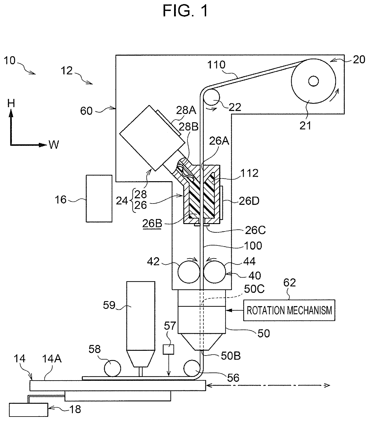
[0016]An exemplary embodiment of the present disclosure will be described below with reference to the drawings. In FIG. 1, arrow H indicates the height direction of the molding apparatus (vertical direction), and arrow W indicates the width direction of the molding apparatus (horizontal direction). The direction intersecting (more specifically, perpendicular to) the height and the width directions of the molding apparatus is the depth direction of the molding apparatus (horizontal direction).

Molding Apparatus

[0017]First, a molding apparatus 10 will be described. FIG. 1 schematically shows the configuration of the molding apparatus 10.

[0018]The molding apparatus 10 shown in FIG. 1 is an apparatus for molding an article. More specifically, the molding apparatus 10 is a three-dimensional molding apparatus (a so-called 3D printer) employing a so-called fused deposition modeling (FDM) method. The molding apparatus 10 molds an article by forming multiple layers with a molding material 100...


PUM

PropertyMeasurementUnit
Radiusaaaaaaaaaa
Heightaaaaaaaaaa

Abstract

A molding apparatus includes: a receiving part on which a wire-shaped molding material that is formed of a bundle of continuous fibers impregnated with resin is discharged; a discharge part that discharges the molding material on the receiving part; and a rotation mechanism that rotates the discharge part to spirally twist the molding material being discharged from the discharge part.

Description

CROSS-REFERENCE TO RELATED APPLICATIONS[0001]This application is based on and claims priority under 35 USC 119 from Japanese Patent Application No. 2019-055054 filed Mar. 22, 2019.BACKGROUND(i) Technical Field[0002]The present disclosure relates to a molding apparatus.(ii) Related Art[0003]International Publication No. 2018 / 151074 discloses a three-dimensional printing apparatus capable of continuously discharging a filament wire, which is formed of a fiber bundle impregnated with resin. The three-dimensional printing apparatus includes a twisting part capable of changing the degree of twisting of the overall filaments or the degree of twisting of the fiber bundle.SUMMARY[0004]In the configuration in which an article is molded from a molding material that is formed of a bundle of continuous fibers spirally twisted and impregnated with resin, the strength of the molding material may decrease.[0005]Aspects of non-limiting embodiments of the present disclosure relate to suppressing dec...

Claims


Application Information

Patent Timeline
IPC IPC(8): B29C64/241B29C64/106B29C64/205
CPCB29C64/205B29C64/106B33Y30/00B33Y10/00B29C64/241B29C64/118B29C64/209B29C64/321B33Y40/00
Inventor AGEISHI, KENTARO
Owner FUJIFILM BUSINESS INNOVATION CORP
Why Eureka
Try Eureka