

Composite material assembly
- Summary
- Abstract
- Description
- Claims
- Application Information
AI Technical Summary
Benefits of technology
Problems solved by technology
Method used
Image

Examples
first embodiment
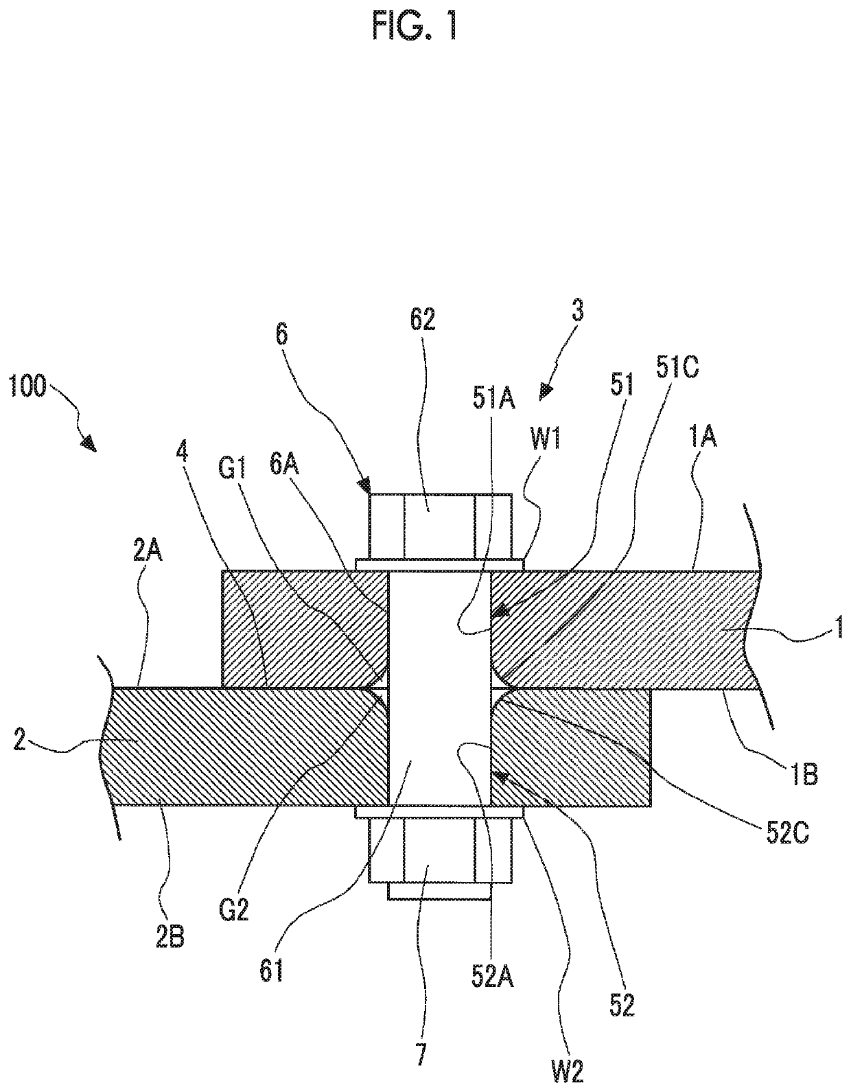
[0024]A first embodiment of the present invention will be described with reference to the drawings. A composite material assembly 100 according to the present embodiment is, for example, a plate member forming a fuselage or a wing of an aircraft. As illustrated in FIG. 1, the composite material assembly 100 includes a first composite material 1, a second composite material 2, and a fastener 3 for connecting these materials.
[0025]The first composite material 1 and the second composite material 2 have a plate shape formed of fiber reinforced plastic (FRP). In configuring a relatively large structure such as a fuselage or wing of an aircraft, a configuration in which a plurality of plate members are connected to each other is often adopted. In the present embodiment, an end portion of the first composite material 1 and an end portion of the second composite material 2 are overlapped with each other in a thickness direction thereof, and the fastener 3 is inserted into a through-hole for...
second embodiment
[0047]Subsequently, a second embodiment of the present invention will be described with reference to FIG. 6. Like configurations similar to those in the first embodiment are denoted by like reference numerals, and detailed description thereof will be omitted. As illustrated in the figure, in a composite material assembly 200 according to the present embodiment, the first chamfered portions 51C are respectively formed on both ends of the first hole 51, and the second chamfered portions 52C are respectively formed on both ends of the second hole 52. Furthermore, first rings 8 and 8′ are respectively attached between the first chamfered portions 51C and the bolt outer peripheral surface 6A, and second rings 9 and 9′ are respectively attached between the second chamfered portions 52C and the bolt outer peripheral surface 6A.
[0048]The first rings 8 and 8′ have an annular shape, and fill gaps G1 and G1 formed between the first chamfered portions 51C and the bolt outer peripheral surface 6...
third embodiment
[0056]Next, a third embodiment of the present invention will be described with reference to FIG. 7. Like configurations similar to those in each of the above-described embodiments are denoted by like reference numerals, and detailed description thereof will be omitted. As illustrated in the figure, in a composite material assembly 300 according to the present embodiment, the first chamfered portion 51C is formed only on the other end edge of the first hole 51, and the second chamfered portion 52C is formed only on one end edge of the second hole 52. The first ring 8 is attached between the first chamfered portion 51C and the bolt outer peripheral surface 6A, and the second ring 9 is attached between the second chamfered portion 52C and the bolt outer peripheral surface 6A. Furthermore, in the present embodiment, the first ring 8 is formed integrally with the first washer W1. The second ring 9 is formed integrally with the second washer W2. Specifically, the first ring 8 is provided ...
PUM
 Abstract
Description
Claims
Application Information