Defibration processing apparatus and fiber processing apparatus

Inactive Publication Date: 2020-09-24
SEIKO EPSON CORP
View PDF0 Cites 5 Cited by
  • Summary
  • Abstract
  • Description
  • Claims
  • Application Information

AI Technical Summary

Problems solved by technology

Therefore, there is a problem in that it is difficult to efficiently discharge the defibrated object.
Further, there is a problem in that when there are many parts wh

Method used


Image

  • Defibration processing apparatus and fiber processing apparatus
  • Defibration processing apparatus and fiber processing apparatus
  • Defibration processing apparatus and fiber processing apparatus

Examples


first embodiment

1. First Embodiment

1-1. Configuration of Defibration Processing Apparatus

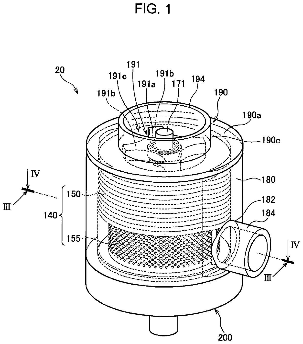
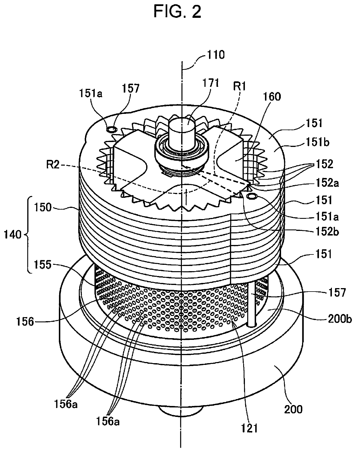
[0027]FIG. 1 is a perspective view of a defibration processing apparatus 20. FIG. 2 is a perspective view of a stationary member 140. FIG. 2 corresponds to a perspective view in which a housing 180 and an upstream cover 190 are omitted from FIG. 1.

[0028]The defibration processing apparatus 20 is an apparatus that performs processing of unwinding a raw material MA, in a state in which a plurality of fibers are bound to each other, into one or a small number of fibers. The defibration processing apparatus 20 is a dry defibration processing apparatus that performs processing such as defibration not in a liquid but in a gas such as the atmosphere and air.

[0029]As illustrated in FIGS. 1 and 2, the defibration processing apparatus 20 according to the present embodiment includes a rotating body 160 that rotates about a rotary shaft 171, and a stationary member 140 that covers the periphery of the rotating body 160. Fu...

second embodiment

2. Second Embodiment

2-1. Configuration of Defibration Processing Apparatus

[0071]Next, a second embodiment of the present disclosure will be described. The same components as those according to the first embodiment are designated by the same reference numerals, and description thereof will be omitted.

[0072]FIG. 5 is a perspective view of a stationary member 240 according to a second embodiment. FIG. 6 is a sectional view of a defibration processing apparatus 220 along an axial direction according to the second embodiment. FIG. 5 corresponds to FIG. 2 of the first embodiment, and FIG. 6 corresponds to FIG. 3 of the first embodiment.

[0073]The defibration processing apparatus 220 according to the second embodiment includes a stationary member 240 instead of the stationary member 140 according to the first embodiment. In the stationary member 240 according to the second embodiment, the fixed outer blade 150 is omitted, and the entirety thereof in the axial direction is configured with a ...

third embodiment

3. Third Embodiment

3-1. Configuration of Defibration Processing Apparatus

[0077]Next, a third embodiment of the present disclosure will be described. The same components as those according to the first embodiment are designated by the same reference numerals, and description thereof will be omitted.

[0078]FIG. 7 is a sectional view of a defibration processing apparatus 320 along an axial direction according to the third embodiment. FIG. 8 is a cross-sectional view of a defibration processing apparatus 320 along a radial direction according to the third embodiment. FIG. 7 corresponds to FIG. 3 of the first embodiment, and FIG. 8 corresponds to FIG. 4 of the first embodiment.

[0079]The defibration processing apparatus 320 according to the third embodiment has a housing 380 instead of the housing 180 according to the first embodiment. In addition to the input port 194 and the discharge port 182, an opening-like gas introduction port 385 the causes the inside and the outside of the housing...


PUM


Abstract

A defibration processing apparatus includes: an input port into which a raw material is input; a rotating body that rotates about a rotary shaft; a stationary member that covers at least part of the rotating body; and a discharge port through which a defibrated object obtained by the rotating body and the stationary member defibrating the raw material is discharged, in which the rotating body has a plurality of rotating blades protruding in a direction away from the rotation center shaft, and the stationary member has a configuration in which a screen having a plurality of openings is disposed in at least part of the stationary member in a direction of the rotation center shaft and surrounds the rotating body in a rotation direction.

Description

[0001]The present application is based on, and claims priority from JP Application Serial Number 2019-053593, filed Mar. 20, 2019, the disclosure of which is hereby incorporated by reference herein in its entirety.BACKGROUND1. Technical Field[0002]The present disclosure relates to a defibration processing apparatus and a fiber processing apparatus.2. Related Art[0003]In the related art, in a defibration processing apparatus and a fiber processing apparatus, a raw material is introduced from an introduction port, is defibrated by an inner blade provided on an outer periphery of a rotating body and an outer blade provided on an inner periphery of a stationary member, and is discharged from a discharge port. For example, in JP-A-2015-74848, defibration is performed with the inner blade of the rotating body disposed between the introduction port and the discharge port in a rotation axis direction and the outer blade of the stationary member covering the entire rotating body in the rotat...

Claims


Application Information

Patent Timeline
IPC IPC(8): D21B1/06B02C18/08B02C23/16
CPCB02C18/08B02C2023/165D21B1/061B02C23/16D21B1/08B27N1/02B27N3/04B27N3/12B27N3/18B27N3/26B07B7/083B07B7/06D21D1/36
Inventor YAMASAKI, KEIGO
Owner SEIKO EPSON CORP
Why Eureka
Try Eureka